
A position correction method, a die cutting method, a position correction device and a die cutting machine

A calibration method and technology of die-cutting machine, which are applied in metal processing and other directions, can solve the problems of insufficient die-cutting accuracy, inability to guarantee accuracy and yield rate, and discarded embossed cardboard, and achieve the effect of improving die-cutting accuracy.

Active Publication Date: 2022-07-05
SHENZHEN HANDWAY IND DIGITAL EQUIP CO LTD
View PDF0 Cites 0 Cited by
  • Summary
  • Abstract
  • Description
  • Claims
  • Application Information

AI Technical Summary

Problems solved by technology

When the time point when the corrugated cardboard reaches the initial cutting position of the die roller is not correct, it will lead to insufficient die-cutting accuracy. If the printing process has been completed in the previous process, it is easy to cause the embossed cardboard to be invalid.
Therefore, the accuracy and yield cannot be guaranteed, which increases unnecessary manufacturing costs

Method used

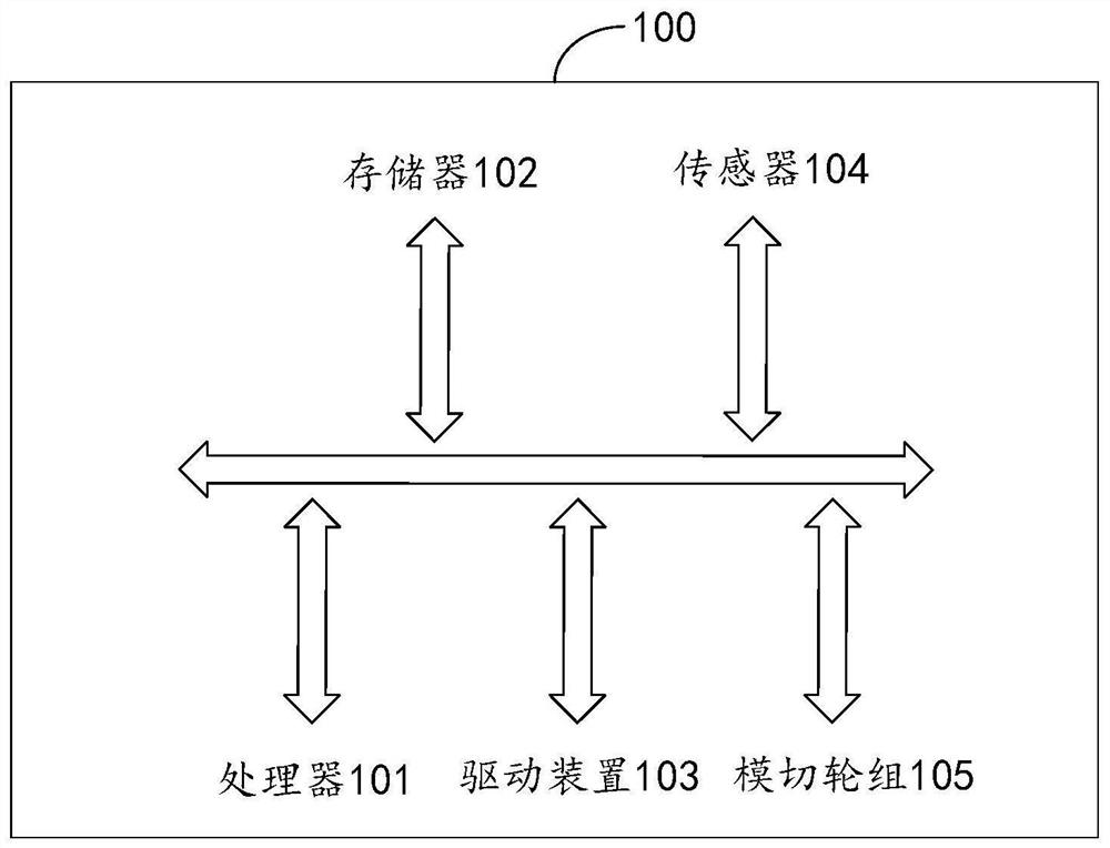
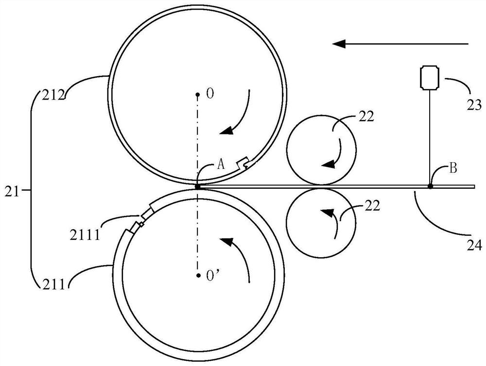
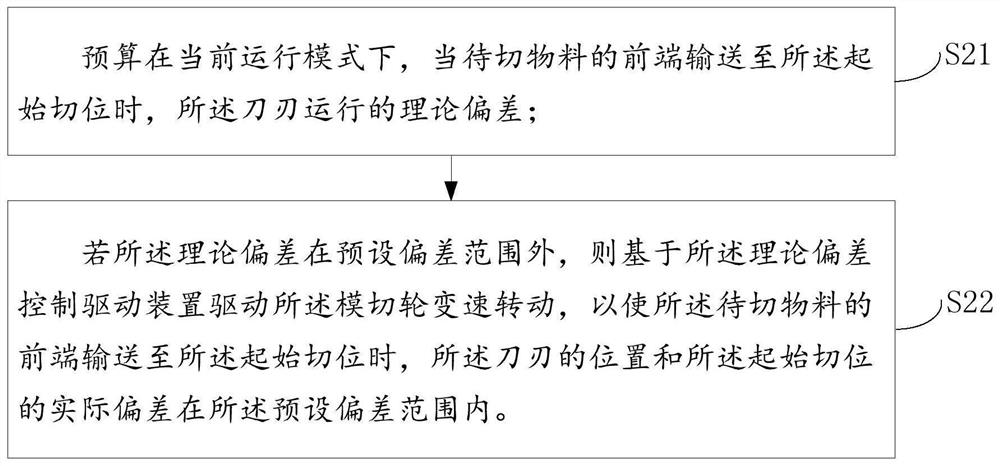

Image

  • A position correction method, a die cutting method, a position correction device and a die cutting machine
  • A position correction method, a die cutting method, a position correction device and a die cutting machine
  • A position correction method, a die cutting method, a position correction device and a die cutting machine

Examples


Embodiment Construction

[0050] In order to make the objectives, technical solutions and advantages of the present invention clearer, the present invention will be further described in detail below with reference to the accompanying drawings and embodiments. It should be understood that the specific embodiments described herein are only used to explain the present invention, but not to limit the present invention.

[0051]It should be noted that, if there is no conflict, various features in the embodiments of the present invention can be combined with each other, which are all within the protection scope of the present invention. In addition, although the functional modules are divided in the schematic diagram of the apparatus, and the logical sequence is shown in the flowchart, in some cases, the division of the modules in the schematic diagram of the apparatus may be different from that in the schematic diagram, or the order in the flowchart may be performed. steps shown or described.

[0052] Unle...


PUM


Abstract

The invention relates to the technical field of die-cutting, in particular to a position correction method, a die-cutting method, a position correction device and a die-cutting machine. The position correction method, the die-cutting method, the device and the die-cutting machine provided by the embodiments of the present invention can estimate that in the current operation mode, when the front end of the material to be cut is conveyed to the initial cutting position, the position of the cutter set on the die-cutting wheel Theoretical deviation of the cutting edge relative to the front end of the material to be cut; if the theoretical deviation of the budget is outside the preset deviation range, the driving device is controlled to drive the die-cutting wheel to rotate at a variable speed based on the theoretical deviation, so that the front end of the material to be cut is transported to the starting point When cutting, the actual deviation between the position of the cutting edge and the initial cutting position is within the preset deviation range. Therefore, in the embodiment of the present invention, by controlling the variable speed movement of the die-cutting wheel, the cutting edge and the front end of the material to be cut can reach the initial cutting position at the same time, thereby improving the die-cutting precision.

Description

technical field [0001] The invention relates to the technical field of die-cutting, in particular to a position correction method, a die-cutting method, a position correction device and a die-cutting machine. Background technique [0002] Corrugated cardboard is widely used in the packaging industry due to its simple production process and low cost. At present, in the process of mass processing corrugated cardboard, a circular die-cutting machine is generally used. The circular die-cutting machine includes a rubber pad roller and a die roller, and the corrugated cardboard is cut and formed under the action of pressure between the rubber pad roller and the die roller. Die-cutting is usually a cutting process in the post-processing of printed matter, which can cut printed matter or other products to the desired shape according to the pre-made graphics. [0003] In the process of realizing the present invention, the inventor found that in the prior art, due to the large inert...

Claims


Application Information

Patent Timeline
Patent Type & Authority Patents(China)
IPC IPC(8): B26D5/00B26F1/38
Inventor 郭晓林彭卫清陈婷李加周江华
Owner SHENZHEN HANDWAY IND DIGITAL EQUIP CO LTD
Learn More