Electric pressure adjusting main machine of die cutting machine

A die-cutting machine, electric technology, applied in metal processing and other directions, can solve the problems of poor versatility of die-cutting machines, insufficient die-cutting thickness, inconvenient replacement of shaft shoulders, etc., and achieves high die-cutting accuracy and versatility. Effect

Inactive Publication Date: 2020-02-07
GUANGDONG FXD INTELLIGENT EQUIP CO LTD
View PDF1 Cites 0 Cited by
  • Summary
  • Abstract
  • Description
  • Claims
  • Application Information

AI Technical Summary

Problems solved by technology

[0004] The die-cutting machine with the above structure uses the motor to drive the cam to move through the transmission mechanism, and then drives the transmission rod to move up and down to make the upper die base move up and down. structure, usually the shape of the curved groove is fixed, which determines that the pressing distance of the upper die base is fixed and cannot be adjusted, which leads to the difference between the cutting knife installed on the upper die base and the lower position when it is pressed down to the limit position. The distance between the mold base is fixed, and the resulting pressure is correspondingly fixed, which cannot be adjusted. Because the precision of die-cutting is very high, if the distance of the cutting knife is slightly larger, the pressure on the product will be greater, which will lead to the failure of die-cutting. The thickness does not meet the requirements, because it is impossible to adjust the pressure. In order to ensure the accuracy, the requirements can only be achieved by replacing the shoulder of the curved groove that meets the requirements, and the replacement of the shoulder is very inconvenient, and each time for different products. Die-cutting needs to replace the shaft shoulder, which leads to poor versatility of the die-cutting machine

Method used


Image

  • Electric pressure adjusting main machine of die cutting machine
  • Electric pressure adjusting main machine of die cutting machine
  • Electric pressure adjusting main machine of die cutting machine

Examples


Embodiment

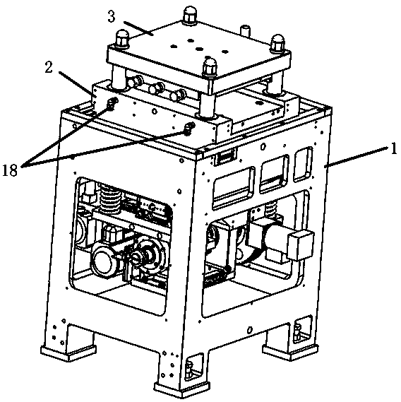
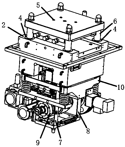
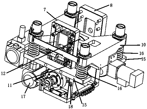
[0029] Please refer to the attached Figures 1 to 4 , the embodiment of the present invention provides an electric voltage regulating main engine of a die-cutting machine, including a frame 1, on which a lower mold base 2 is fixed, and the lower mold base 2 is a fixed mold base, and the lower mold base 2 Guide sleeves 4 are arranged on the four corners, and an upper mold base 3 is arranged parallelly above the lower mold base 2. The upper mold base 3 is a movable mold base, and the upper mold base 3 is provided with a die mounting hole 5 , the cutting die mounting hole 5 can be used to install the cutting die, the upper die base 3 is fixed on four movable guide pillars 6 vertically arranged with the upper die holder 3, the movable guide pillars 6 are movably connected with the guide sleeve 4, That is, the movable guide post 6 can move up and down in the guide sleeve 4, and the lower end of the movable guide post 6 passes through the guide sleeve 4 and is connected to the lifti...


PUM


Abstract

The invention provides an electric pressure adjusting main machine of a die cutting machine, and belongs to the field of die cutting equipment. The electric pressure adjusting main machine of the diecutting machine comprises a machine frame. A lower die holder is fixed to the machine frame and is a fixed die holder. Guide sleeves are arranged at the four corners of the lower die holder. An upperdie holder is further arranged above the lower die holder in a parallel mode, cutter die installation holes are formed in the upper die holder, and the upper die holder is fixed to four moving guide columns which are arranged in the mode of being perpendicular to the upper die holder. The moving guide columns are movably connected with the guide sleeves, and the lower ends of the moving guide columns pass through the guide sleeves and are connected to a lifting base. A left support and a right support are connected with the side of the lower die holder, bearings are fixed to the left support and the right support, and a lifting mechanism which is used for adjusting the lifting base to ascend and descend is arranged on the bearings. A pressure adjusting mechanism which is used for adjustingthe pressure of die cutting is arranged at the bottom of the lifting base, and the lifting mechanism and the pressure adjusting mechanism are connected in a transmission mode. compared with the priorart, the electric pressure adjusting main machine of the die cutting machine has the advantages that the pressure formed by a cutter to a product can be adjusted so as to guarantee the die cutting accuracy, part replacement is not required, and the universality is higher.

Description

technical field [0001] The invention belongs to the field of die-cutting equipment, and in particular relates to an electric voltage-regulating host of a die-cutting machine. Background technique [0002] Die Cutting Machine (Die Cutting Machine), also known as beer machine, cutting machine, CNC stamping machine, is mainly used for die cutting of some corresponding non-metallic materials, self-adhesive, EVA, double-sided adhesive tape, electronics, mobile phone rubber pads, etc. (full break, half break), indentation and bronzing operations, lamination, automatic waste discharge, die-cutting machines use steel knives, metal molds, steel wires (or templates carved from steel plates), and apply certain pressure through the embossing plate , Cut the printed matter or cardboard into a certain shape. It is an important equipment for post-press packaging processing and molding. [0003] The invention patent with the patent number of 201010203189.6 discloses a method related to a ...

Claims


Application Information

Patent Timeline
IPC IPC(8): B26D5/00B26D5/08B26D7/26B26F1/38
CPCB26D5/00B26D5/086B26D7/2628B26F1/38
Inventor 侯立新王夏兵
Owner GUANGDONG FXD INTELLIGENT EQUIP CO LTD
Why Eureka
Try Eureka