
Automatic translation mechanism of die-cutting rubber pad roller

A technology of traversing mechanism and die-cutting glue, applied in the field of mechanical parts, can solve the problems of fast wear of die-cutting rubber pad roller, high cost, affecting die-cutting accuracy, etc., so as to improve die-cutting accuracy, prolong service life and facilitate maintenance. Effect

Inactive Publication Date: 2010-05-26
深圳市科发机械制造有限公司
View PDF0 Cites 0 Cited by
  • Summary
  • Abstract
  • Description
  • Claims
  • Application Information

AI Technical Summary

Problems solved by technology

However, due to the high-frequency contact between the die-cutting rubber pad roller and the die-cutting knife during the production process, the wear is too fast, which directly affects the production cost of the die-cutting machine
[0003] At present, hydraulic pressure is used to drive the die-cutting rubber backing roller to move horizontally automatically, which is costly. The ratio of the cutting movement speed to the rotation speed of the die-cutting rubber backing roller is variable, so the die-cutting rubber backing roller wears quickly, which also affects the die-cutting. precision
The crank linkage mechanism used at the same time on the market drives the die-cutting rubber pad roller to move automatically, resulting in uneven traverse speed of the die-cutting rubber pad roller, which affects the precision of die-cutting and the service life of the die-cutting rubber pad

Method used


Image

  • Automatic translation mechanism of die-cutting rubber pad roller
  • Automatic translation mechanism of die-cutting rubber pad roller
  • Automatic translation mechanism of die-cutting rubber pad roller

Examples


Embodiment Construction

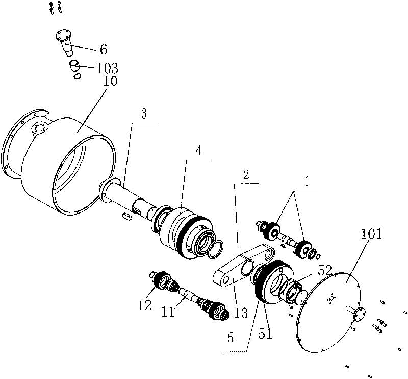
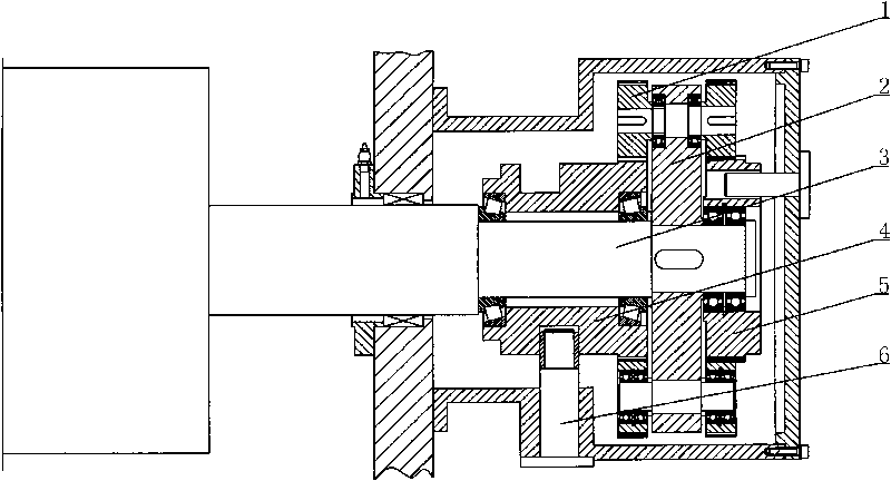
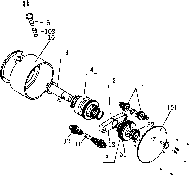
[0021] Such as Figure 1-2 As shown, a die-cutting rubber pad roller automatic traverse mechanism, which consists of a planetary gear 1, a planetary carrier 2, a die-cutting rubber pad roller 3, a movable center wheel 4, a fixed center wheel 5, and a positioning shaft 6. The planetary carrier 2 Fixed on the die-cut rubber pad roller 3, the planetary gear 1 is installed on the planet carrier 2. The planetary gear 1 is composed of a gear 11 and a shaft 12 . The fixed center wheel 5 is provided with a cam 51 and a spacer 52 . There are two planetary gears 1 installed on the planet carrier 2 through a connecting rod 13 . When the present invention is installed, the planet carrier 2 is fixed on the die-cutting rubber pad roller 3, the planetary gear 1 is installed on the planet carrier 2, and connected to the movable center wheel 4, the fixed center wheel 5, and the positioning shaft 6, and the above-mentioned assembly is completed Afterwards, it is installed and fixed in a gear c...


PUM


Abstract

The invention discloses an automatic translation mechanism of a die-cutting rubber pad roller, comprising a planetary gear, a planet carrier, a die-cutting rubber pad roller, a movable center wheel, a fixed center wheel and a positioning shaft. The planet carrier is fixed on the die-cutting rubber pad roller; the planetary gear is mounted on the planet carrier and comprises a gear and a shaft; the fixed center wheel is provided with a cam and a separator sleeve; the planet carrier is fixed on the die-cutting rubber pad roller; and the planetary gear is mounted on the planet carrier and connected with the movable center wheel, the fixed center wheel and the positioning shaft which are assembled, mounted and fixed in a gearbox; the gear box is dustproof by a gearbox cover and is locked by the positioning shaft and the shaft sleeve. The invention has simple and practical structure and extremely convenient maintenance in the use process, balances translation by rotating the die-cutting rubber pad roller along, effectively prolongs the service life of the die-cutting rubber pad roller and improves the die-cutting precision thereof.

Description

technical field [0001] The invention relates to a mechanical part produced by die-cutting and forming of a corrugated box, in particular to an automatic lateral movement mechanism of a die-cutting rubber pad roller. Background technique [0002] The circular die-cutting production process of corrugated cartons has been developed more and more widely in the production of cartons due to its high efficiency and low cost. However, due to the high-frequency contact between the die-cutting rubber pad roller and the die-cutting knife during the production process, the wear is too fast, which directly affects the production cost of the die-cutting machine. [0003] At present, hydraulic pressure is used to drive the die-cutting rubber backing roller to move horizontally automatically, which is costly. The ratio of the cutting movement speed to the rotation speed of the die-cutting rubber backing roller is variable, so the die-cutting rubber backing roller wears quickly, which also a...

Claims


Application Information

Patent Timeline
Patent Type & Authority Applications(China)
IPC IPC(8): B31B1/20B31B50/20
Inventor 刘尚忠
Owner 深圳市科发机械制造有限公司
Learn More