Swing stem shield device for die-cutting machine

A die-cutting machine and shield technology, applied in metal processing and other directions, can solve the problems of low die-cutting accuracy, inaccurate die-cutting position, and high die-cutting scrap rate, and achieves short adjustment time, accurate die-cutting position, High precision die-cutting effect

Inactive Publication Date: 2013-03-20
DALIAN XINKE MACHINERY
View PDF0 Cites 0 Cited by
  • Summary
  • Abstract
  • Description
  • Claims
  • Application Information

AI Technical Summary

Problems solved by technology

According to the different embossing forms, the die-cutting machine is mainly divided into three basic types: flat type, circular type and trapped round type. The swing rod shield of the die-cutting machine is an important part of the die-cutting machine. The traditional die-cutting machine The structure of the machine guard is complex, it is not easy to install, and the overall layout is unreasonable, resulting in the overall installation of the die-cutting machine and the complex mechanism, resulting in inconvenient operation, low die-cutting accuracy, long adjustment time, inaccurate die-cutting position, and low accuracy. The high window die-cutting waste rate is high, the function is single, and continuous die-cutting cannot be performed, etc.

Method used


Image

  • Swing stem shield device for die-cutting machine
  • Swing stem shield device for die-cutting machine
  • Swing stem shield device for die-cutting machine

Examples


Embodiment Construction

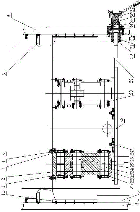
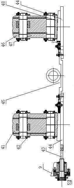
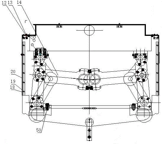
[0012] Die-cutting machine pendulum shield device structure of the present invention is as follows Figure 1-3 As shown, the front part between the transmission surface wallboard 7 and the operation surface blocking plate 9 is installed with a long-drawn main board 53, and the long-drawn main board 53 is installed on the operation surface blocking plate 9 through the second pressure regulating screw 29, and is located on the operation surface blocking plate 9. A pressure regulating sprocket 35 is installed on the external second pressure regulating screw 29, a knob shaft 36 and a knob 37 are installed at the end of the pressure regulating sprocket 35, an adjusting nut 30 is installed on the second pressure regulating screw 29, and a sealing sleeve is installed on the outside of the regulating nut 30 31. A washer 32 is installed at the end of the sealing sleeve 31, and a retaining sleeve 34 is installed at the end of the pressure regulating sprocket 35. Slant iron 26,28 is inst...


PUM


Abstract

The invention discloses a swing stem shield device for a die-cutting machine. A long pulling main plate is arranged on a front part between a driving face wall plate and an operating face plugging plate; the long pulling main plate is arranged on the operating face plugging plate through a second pressure-regulating screw rod; wedges are arranged on the long pulling main plate; lower shaft seats are arranged on the upper part of the wedge; upper and lower connecting shafts are arranged on the upper parts of the lower shaft seats; lower swing arms are arranged on the upper parts of the upper and lower connecting shafts; middle connecting shafts are arranged on the upper parts of the lower swing arms; upper swing arms are arranged on the upper parts of the middle connecting shafts; the upper parts of the upper swing arms are connected with upper shaft seats; and connecting rod combinations are arranged among the front and back four swing arms. The swing stem shield device for the die-cutting machine disclosed by the invention is simple in structure, and is reasonable in layout, so that the die-cutting machine has the advantages of easiness for installing as a whole, convenience in operating, high die-cutting accuracy, low time consumption on debugging, accurate die-cutting position, high accuracy and low windowing and die-cutting rejection rates.

Description

technical field [0001] The invention relates to the field of post-press processing equipment, in particular to a die-cutting machine device for post-press processing. Background technique [0002] Die-cutting machine is mainly used for die-cutting, indentation and bronzing of some non-metallic materials, self-adhesive, double-sided tape, electronics, mobile phone pads, etc. It is an important equipment for post-press packaging processing. The main parts of the die-cutting machine are the die-cutting platen and the press-cutting mechanism. The processed sheet is between the two, and the finishing technology of die-cutting is completed under the action of pressure. According to the different embossing forms, the die-cutting machine is mainly divided into three basic types: flat type, circular type and trapped round type. The swing rod shield of the die-cutting machine is an important part of the die-cutting machine. The traditional die-cutting machine The structure of the mac...

Claims


Application Information

Patent Timeline
Patent Type & Authority Applications(China)
IPC IPC(8): B26D7/22
Inventor 李东升
Owner DALIAN XINKE MACHINERY
Why Eureka
Try Eureka