
High-precision corrugated paper die cutting device based on rigid contact

A rigid contact, high-precision technology, applied in metal processing and other directions, can solve problems such as the inability to effectively improve die-cutting accuracy, corrugated cardboard misalignment, offset, affecting product quality, etc., to achieve stable molding effect, avoid offset, use The method is simple and easy to operate

Active Publication Date: 2021-09-17
GUANGZHOU KESHENGLONG CARTON PACKING MACHINE
View PDF8 Cites 0 Cited by
  • Summary
  • Abstract
  • Description
  • Claims
  • Application Information

AI Technical Summary

Problems solved by technology

However, in practical applications, with the continuous grinding and repair of the rubber pad roller, its surface accuracy will actually continue to decline; in addition, because the surface layer of the rubber pad roller is still a flexible rubber pad material, during the die-cutting process, with the The surface layer of the rubber backing roller is squeezed, and the corrugated cardboard is prone to misalignment and offset, especially for large corrugated cardboard. This phenomenon is more obvious, which leads to the inability to effectively improve the die-cutting accuracy and easily affects product quality.

Method used


Image

  • High-precision corrugated paper die cutting device based on rigid contact
  • High-precision corrugated paper die cutting device based on rigid contact
  • High-precision corrugated paper die cutting device based on rigid contact

Examples


Embodiment 1

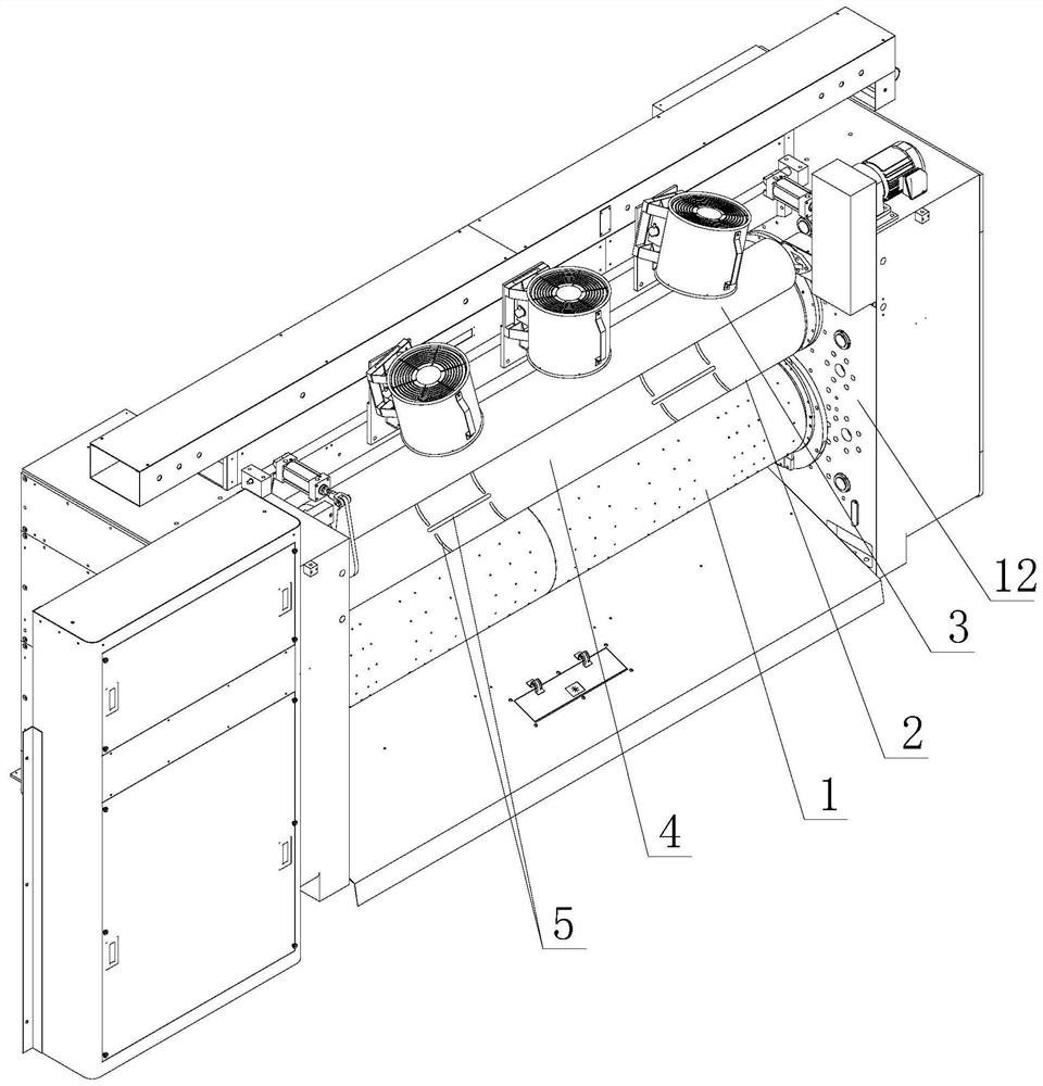
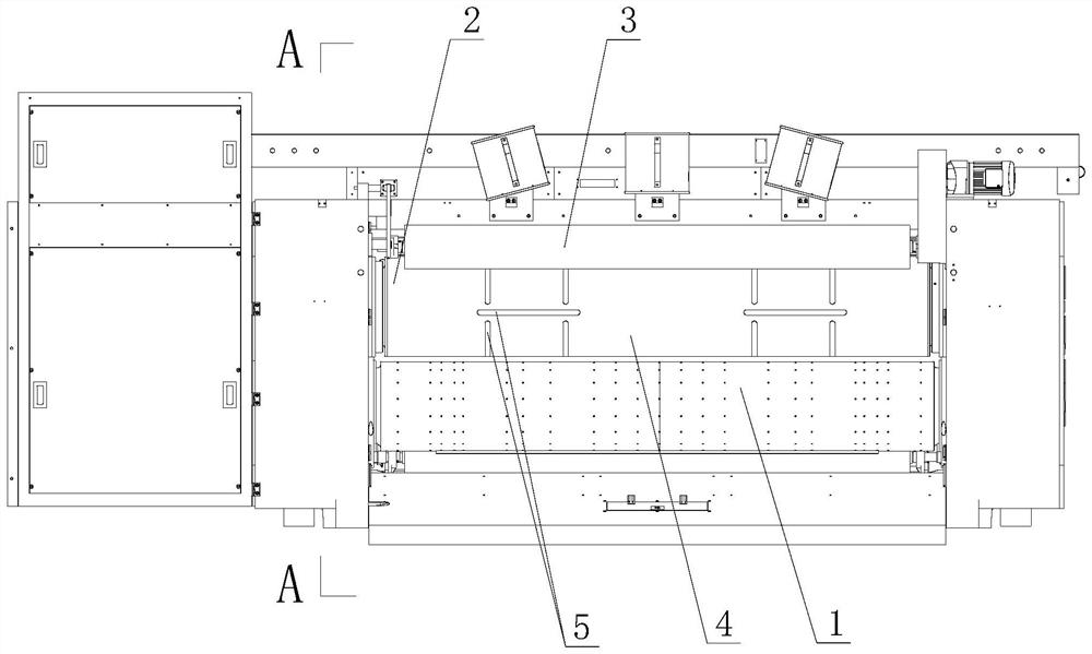
[0033] In this embodiment, a high-precision corrugated paper die-cutting device based on rigid contact, such as figure 1 or figure 2 As shown, it includes a die-cutting roller 1 and a backup roller 2 that cooperate and form a die-cutting roller group (in this embodiment, one side of the backup roller is also provided with a waste cleaning brush roller 3), and a die-cutting plate is installed on the die-cutting roller (not shown in the figure), protruding knife lines and pressure lines are distributed on the die-cutting board, a rigid backing plate 4 is installed on the backup roller, and several die-cutting grooves 5 are distributed on the rigid backing plate; When cutting, the knife line and the surface of the rigid backing plate are correspondingly located on the upper and lower sides of the corrugated cardboard for die-cutting operations, and the crimping line and die-cutting grooves are correspondingly located on the upper and lower sides of the corrugated cardboard for i...

Embodiment 2

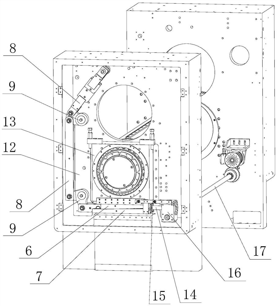
[0038]This embodiment is a high-precision corrugated cardboard die-cutting device based on rigid contact. Compared with Embodiment 1, the difference is that: in the fixing structure on both sides of the rigid backing plate, the fixing structure includes axial fixing strips and keyholes. , elastic fixing strips and lock buckles; one side of the rigid backing plate is provided with fixed installation holes, and each fixed installation hole is pressed and fixed on the backing roller by the axial fixing strip, and the other side of the axial fixing strip and the rigid backing plate There are one-to-one corresponding lock holes on the sides, and the two ends of the elastic fixing strips are respectively equipped with lock buckles. connect. When installing the rigid backing plate, press and fix one side of the backing roller along the axial direction of the backing roller through the axial fixing strip, and then roll the rigid backing plate to cover the surface of the backing roller...

Embodiment 3

[0040] This embodiment is a high-precision corrugated cardboard die-cutting device based on rigid contact, which is suitable for die-cutting processing of large or super-large corrugated cardboard. Compared with Example 1, the difference is that there are also Auxiliary installation holes, when in use, can further strengthen the installation stability of the rigid backing plate on the backing roller through the auxiliary installation holes.


PUM


Abstract

The invention discloses a high-precision corrugated paper die cutting device based on rigid contact. The high-precision corrugated paper die cutting device comprises a die cutting roller and a cushion roller which are matched with each other, a die cutting plate is installed on the die cutting roller, outwards-protruding cutter lines and pressing lines are distributed on the die cutting plate, a rigid cushion plate is installed on the cushion roller, and a plurality of die cutting grooves are distributed in the rigid cushion plate. When a corrugated board is subjected to die cutting, the cutter lines and the surface of the rigid cushion plate are correspondingly located on the upper side and the lower side of the corrugated board for die cutting operation, the pressing lines and the die cutting grooves are correspondingly located on the upper side and the lower side of the corrugated board for indentation operation, and the cutter lines and the pressing lines on the die cutting board are in rigid contact with the rigid cushion plate. The rigid cushion plate is installed on a cushion roller to replace a traditional rubber cushion roller for use, the die cutting grooves are formed in the rigid cushion plate, in the application process, on one hand, rigid contact is formed between the cutter lines and the rigid cushion plate, the phenomena of deviation, dislocation and the like of corrugated boards can be effectively avoided, on the other hand, the die cutting grooves are matched with the pressing lines, and the indentation with accurate positioning can be ensured to be formed.

Description

technical field [0001] The invention relates to the field of corrugated paper printing equipment, in particular to a high-precision corrugated paper die-cutting device based on rigid contact. Background technique [0002] In the process of corrugated cardboard printing and processing for packaging, corrugated cardboard often needs to obtain pre-designed shapes or cut marks. Therefore, die-cutting machines are one of the essential equipment for corrugated cardboard printing and processing. As the core mechanism of the die-cutting machine, the die-cutting roller group is mainly composed of a matching die-cutting roller and a rubber pad roller. When the corrugated cardboard passes through the gap between the die-cutting roller and the rubber pad roller, cutting marks and indentations are formed on the corrugated cardboard by using the knife line and the pressing line respectively. [0003] In the die-cutting roller set of a traditional die-cutting machine, since the surface la...

Claims


Application Information

Patent Timeline
Patent Type & Authority Applications(China)
IPC IPC(8): B26F1/44B26D7/26
CPCB26F1/44B26D7/2628B26D7/2614B26F2001/4418B26F2001/4445Y02P70/10
Inventor 何国胜张裕彬陈永生
Owner GUANGZHOU KESHENGLONG CARTON PACKING MACHINE
Learn More