Illuminating lamp installed on bed head

A lighting and bedside technology, applied to lighting devices, non-electric lighting devices, fixed lighting devices, etc., can solve the problems that the bedside lighting cannot be moved and cannot be adjusted

Active Publication Date: 2021-04-20
江门市健明灯饰有限公司
View PDF25 Cites 2 Cited by
  • Summary
  • Abstract
  • Description
  • Claims
  • Application Information

AI Technical Summary

Problems solved by technology

[0005] In order to overcome the shortcomings of general bedside lighting that cannot be moved and cannot be adjusted, the technical problem to be solved is: to provide a lighting installed on the bedside that can move and change the light.

Method used


Image

  • Illuminating lamp installed on bed head
  • Illuminating lamp installed on bed head
  • Illuminating lamp installed on bed head

Examples


Embodiment 1

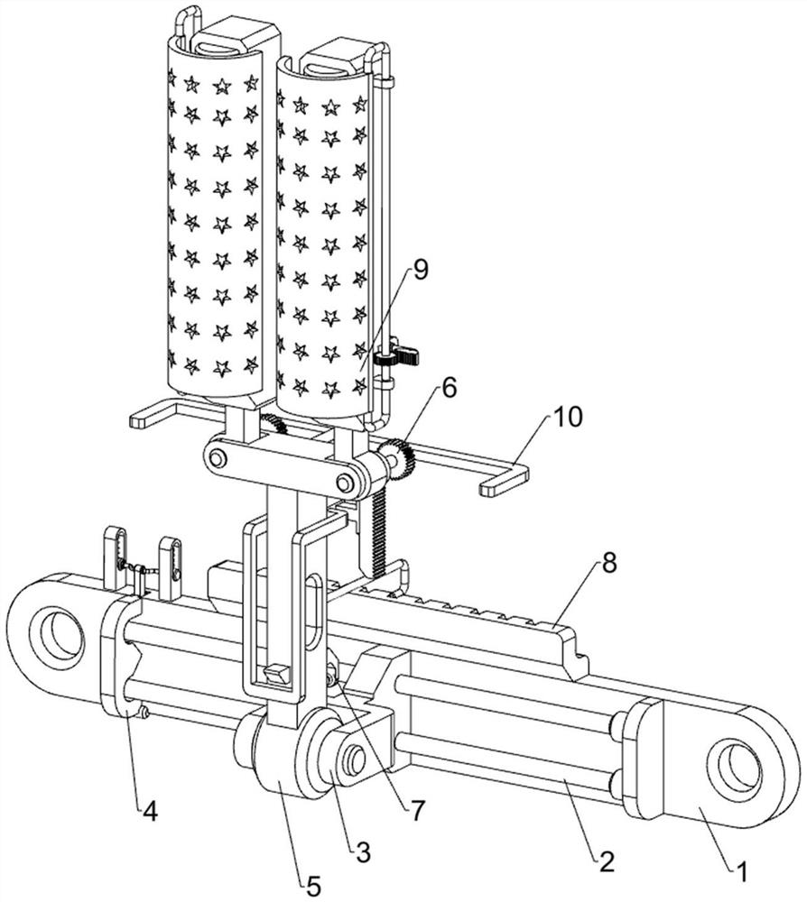
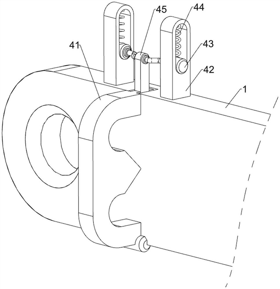
[0028] A lighting lamp installed at the head of the bed, such as Figure 1 to Figure 3 As shown, it includes a mounting plate 1, a cross bar 2, a connecting frame 3, a disassembly assembly 4, and a lighting assembly 5. The front part of the mounting plate 1 is connected to the upper and lower sides of the cross bar 2, and the cross bars 2 are slidably connected to each other. Frame 3, the left side of the mounting plate 1 is provided with a disassembly assembly 4, and the connecting frame 3 is provided with a lighting assembly 5.

[0029] When the device needs to be used, the device is installed on the wall through the mounting plate 1, and then the lighting assembly 5 can be started for lighting. The lighting assembly 5 moves. When lighting is not needed, the lighting assembly 5 is controlled to recover through the connection frame 3, and then the lighting assembly 5 can be turned off. When the lighting assembly 5 needs to be replaced, the disassembly assembly 4 can be contro...

Embodiment 2

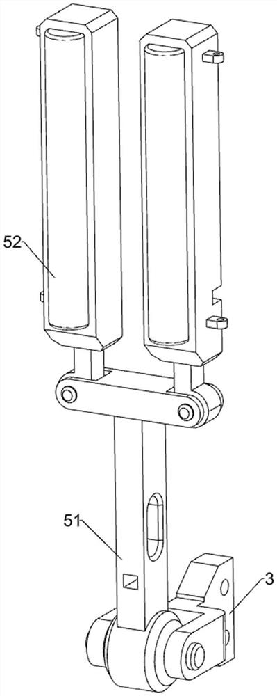
[0035] On the basis of Example 1, such as figure 1 , Figure 4 , Figure 5 , Figure 6 , Figure 7 and Figure 8 As shown, a swing assembly 6 is also included, and the swing assembly 6 includes a first slider 62, a second spring 63, a pull plate 64, a first rack 65 and a first gear 66, and the rear side of the bracket 51 is provided with a first A chute 61, the first chute 61 is slidably provided with a first slide block 62, a second spring 63 is connected between the first slide block 62 and the first chute 61, and a pull plate is connected on the first slide block 62 64 , the first rack 65 is connected to the left and right sides of the first slider 62 , and the first gear 66 is connected to the lower rear side of the lighting lamps 52 on both sides, and the first gear 66 meshes with the first rack 65 .

[0036] Start the lighting lamp 52 for lighting. When it is necessary to control and increase the lighting range, the pull plate 64 can be controlled to move upward, so...


PUM


Abstract

The invention relates to an illuminating lamp, in particular to an illuminating lamp installed on a bed head. The technical problem to be solved by the invention is to provide the illuminating lamp which can move and change light and is mounted on the bed head. The illuminating lamp mounted on a bed head comprises a mounting plate; cross rods mounted on the two sides of the mounting plate; a connecting frame mounted between the cross rods in a sliding manner; a dismounting assembly mounted on the mounting plate; and a lighting assembly mounted on the connecting frame. By rotating the illuminating lamp, the illuminating range is enlarged, the illuminating effect is better, and the illuminating lamp is further provided with the swing assembly, so that a user can rotate the illuminating lamp more conveniently; by controlling the connecting frame to move, the position of the illuminating lamp can be changed, and meanwhile the positioning assembly can fix the position of the illuminating lamp through cooperation of the clamping grooves and the clamping rods.

Description

technical field [0001] The invention relates to an illuminating lamp, in particular to an illuminating lamp installed at the head of a bed. Background technique [0002] Lighting lamps are a common lighting tool in life. Lighting lamps have many shapes and performances, which can make them have their own place in a warm home. [0003] The general bedside lighting can only be fixed in one place, so that the bedside lighting cannot be moved, and then when the layout of the bedroom needs to be adjusted, it will affect the overall layout aesthetics, and the lighting cannot be adjusted, it can only be used for lighting. When it is necessary to create a warm atmosphere, it is necessary to install other types of lighting in the bedroom, which cannot achieve energy-saving effects. [0004] Therefore need to design a kind of lighting lamp that can move and change light and be installed on the head of a bed. Contents of the invention [0005] In order to overcome the disadvantages...

Claims


Application Information

Patent Timeline
Patent Type & Authority Applications(China)
IPC IPC(8): F21S8/00F21V21/14F21V1/00
Inventor 欧阳可爱
Owner 江门市健明灯饰有限公司
Why Eureka
Try Eureka