Insulating paperboard tensile strength test fixture

A tensile strength and test fixture technology, applied in the direction of strength characteristics, the use of stable tension/pressure test material strength, instruments, etc., can solve the problems of cumbersome operation, occupying test time, affecting test work efficiency, etc.

Pending Publication Date: 2021-04-20
江西铭源电气有限公司
View PDF10 Cites 1 Cited by
  • Summary
  • Abstract
  • Description
  • Claims
  • Application Information

AI Technical Summary

Problems solved by technology

In this process, the operation of adjusting the distance between the two chucks and clamping the sample is usually cumbersome. Usually, one test subject needs to test multiple samples, and the distance between the chucks needs to be completed when each sample is tested. Operations such as adjustment, measurement, and clamping often take up a large part of the test time during on-site testing, which seriously affects the test work efficiency

Method used


Image

  • Insulating paperboard tensile strength test fixture
  • Insulating paperboard tensile strength test fixture
  • Insulating paperboard tensile strength test fixture

Examples


Embodiment Construction

[0016] In order to facilitate the understanding of the present invention, the present invention will be described more fully below with reference to the associated drawings. A preferred embodiment of the invention is shown in the drawings. However, the present invention can be embodied in many different forms and is not limited to the embodiments described herein. Rather, these embodiments are provided so that the disclosure of the present invention will be thorough and complete.

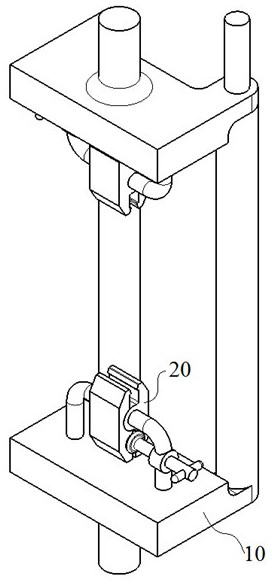
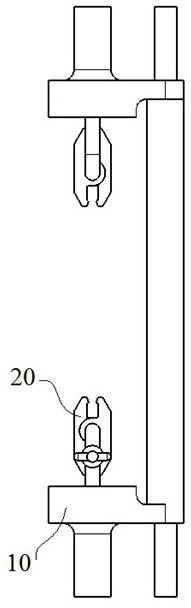
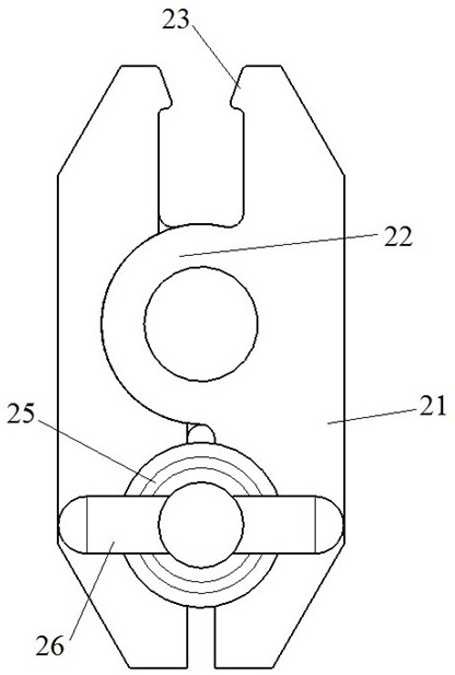
[0017] see Figure 1-Figure 4 The shown insulating cardboard tensile strength test fixture comprises a bracket 10 and a chuck 20, the chuck 20 is installed on the bracket 10, the bracket 10 is installed on a tensile machine, the bracket 10 and the chuck 20 have two groups, the bracket 10 and the clamp After the heads 20 are combined, they are respectively installed at the upper and lower ends of the tensile machine to form the upper clamping part and the lower clamping part of the sample.

[0018...


PUM


Abstract

An insulating paperboard tensile strength test fixture belongs to the technical field of transformer insulating part production and comprises two groups of supports and two groups of chucks, wherein the chucks are mounted on the supports, and the supports are mounted on a tensile machine. The support comprises a main table, a guide rod, a limiting boss, a guide lug, a connecting rod and a threaded hole, wherein the main table is of a main connecting structure of the support, the guide rod is arranged on the rear side of the main table, the limiting boss is arranged on the guide rod, and the guide lug is arranged at the other end, opposite to the guide rod, of the rear side of the main table; the connecting rod is arranged on the main table in the same extending direction as the guide rod; the chucks are installed on the connecting rods, and the threaded holes are formed in one sides of the connecting rods. Each chuck is composed of two symmetrical clamping plates, wherein the two clamping plates are installed in a staggered mode to form the chuck; each clamping plate comprises a clamping body, a shaft barrel, a semi-conical hole and a conical rod, wherein the shaft barrel is arranged in the middle of the clamping body and installed on the connecting rod, the semi-conical hole is formed in the bottom of the clamping body, the conical rod comprises a conical head and a screw rod, the screw rod is installed in threaded hole, and the conical head is sleeved in the semi-conical hole.

Description

technical field [0001] The invention belongs to the technical field of transformer insulating parts production, and in particular relates to a jig for testing the tensile strength of insulating cardboard. Background technique [0002] A large number of insulating parts are required in the manufacturing process of transformers. The use of insulating parts in transformers usually has its own technical performance requirements. It can only be used on transformers after passing necessary performance tests and passing the test. One of the test contents is tensile strength. strength test. In the tensile strength test of insulating cardboard, it is first necessary to cut several strip samples of 50mm×200mm, adjust the distance between the two chucks of the standard tensile machine with automatic counting to 100mm, and start the test after clamping. In this process, the operation of adjusting the distance between the two chucks and clamping the sample is usually cumbersome. Usually...

Claims


Application Information

Patent Timeline
IPC IPC(8): G01N3/04G01N3/08
Inventor 冯斌喻涛华
Owner 江西铭源电气有限公司
Why Eureka
Try Eureka