
A light spot detection method, device, electronic equipment and readable storage medium

A light spot detection and light spot technology, applied in the field of image processing, can solve the problems of large memory consumption, small storage space and time-consuming

Active Publication Date: 2021-08-24
轻威科技(绍兴)有限公司
View PDF18 Cites 0 Cited by
  • Summary
  • Abstract
  • Description
  • Claims
  • Application Information

AI Technical Summary

Problems solved by technology

[0005] In view of this, the purpose of this application is to provide a spot detection method, device, electronic equipment and readable storage medium, which can simultaneously detect spots on the detection image through a set of algorithms, and solve the problem of large memory consumption in the prior art. problem, to achieve the effect of simple algorithm, small storage space and less time-consuming, accurate and stable extraction of spot center point

Method used


Image

  • A light spot detection method, device, electronic equipment and readable storage medium
  • A light spot detection method, device, electronic equipment and readable storage medium
  • A light spot detection method, device, electronic equipment and readable storage medium

Examples


Embodiment Construction

[0052] In order to make the purpose, technical solutions and advantages of the embodiments of the present application clearer, the technical solutions in the embodiments of the present application will be clearly and completely described below in conjunction with the drawings in the embodiments of the present application. Obviously, the described embodiments are only It is a part of the embodiments of this application, not all of them. The components of the embodiments of the application generally described and illustrated in the figures herein may be arranged and designed in a variety of different configurations. Accordingly, the following detailed description of the embodiments of the application provided in the accompanying drawings is not intended to limit the scope of the claimed application, but merely represents selected embodiments of the application. Based on the embodiments of the present application, every other embodiment obtained by those skilled in the art withou...


PUM


Abstract

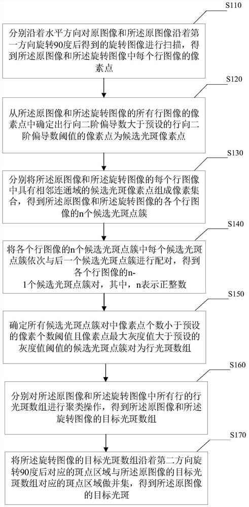
The present application provides a spot detection method, device, electronic equipment and readable storage medium, respectively scanning the original image and the rotated image obtained after the original image is rotated 90 degrees along the first direction along the horizontal direction to obtain the original image and the pixels of each row image in the rotated image, determine the candidate flare pixels, form a row flare array with all the candidate flare pixels that meet the preset requirements in each row image, and cluster all the row flare arrays respectively, Obtain the target spot array of the original image and the rotated image, and combine the corresponding spot area after the target spot array of the rotated image is rotated 90 degrees along the second direction with the spot area corresponding to the target spot array of the original image to obtain the original image Target spot. The application can simultaneously detect the spot on the detection image through a set of algorithms, solve the problem of large memory consumption, and achieve the effect of simple algorithm, small storage space and less time consumption, and accurate and stable extraction of the center point of the spot.

Description

technical field [0001] The present application relates to the technical field of image processing, in particular, to a spot detection method, device, electronic equipment and readable storage medium. Background technique [0002] With the development of infrared imaging technology, more and more infrared imaging technology is applied to various industries, involving monitoring, fire protection and military and other aspects. For example, using an infrared camera to detect and identify objects with a monocular camera or optical measurement based on computer vision technology. [0003] A typical infrared image is a two-dimensional projection image containing several infrared light marker points with different distances in the scene. Reflected light spots affect the quality of infrared imaging. In order to solve the problem of light spots in infrared images, it is necessary to detect light spots first. [0004] In the common spot detection algorithms, no matter the detection ...

Claims


Application Information

Patent Timeline
Patent Type & Authority Patents(China)
IPC IPC(8): G06T7/00G06T3/60G06K9/62
Inventor 郭路晗黄永鑫
Owner 轻威科技(绍兴)有限公司
Learn More