Calibration method and device and electronic equipment
What is AI technical title?
AI technical title is built by Patsnap AI team. It summarizes the technical point description of the patent document.
A calibration method and a calibration parameter technology, applied in the field of computer vision, can solve problems such as large gaps in monitoring results and affecting monitoring accuracy
Pending Publication Date: 2021-04-20
SHANGHAI SENSETIME INTELLIGENT TECH CO LTD
View PDF0 Cites 0 Cited by
Summary
Abstract
Description
Claims
Application Information
AI Technical Summary
This helps you quickly interpret patents by identifying the three key elements:
Problems solved by technology
Method used
Benefits of technology
Problems solved by technology
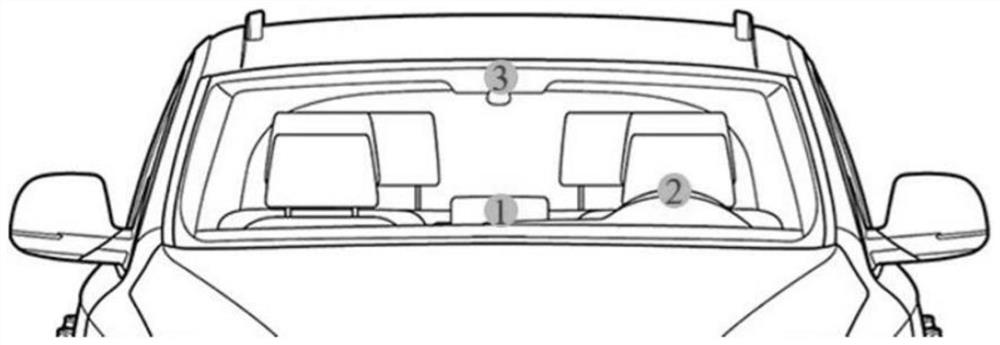
Taking intelligent driving as an example, the above-mentioned monitoring function uses the driver's head posture and eye sight data. When the driver drives a different model or the camera of the monitoring system is installed at different positions in the same cabin, fixed calibration parameters are used. It will lead to a large gap in monitoring results and affect the accuracy of monitoring
Method used
Image
Click on the blue label to locate the original text in one second.
Reading with bidirectional positioning of images and text.
Examples
Embodiment approach 1
[0169] Embodiment 1. The system automatically selects the target calibration mode
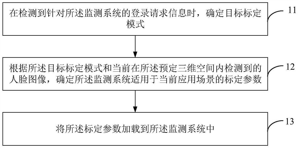
[0170] In an embodiment of the present application, the above step 11 may specifically be: when the login request information is detected, determining a preset calibration mode as the target calibration mode.
[0171] Wherein, the preset calibration mode in the embodiment of the present application may include: a real-time calibration mode, a history matching mode, and a default calibration mode.
[0172] In the embodiment of the present application, the calibration mode adopted by the DMS may be preset, and when the system detects the above login request information, it will automatically determine the preset calibration mode as the target calibration mode.
[0173] Exemplarily, assuming that the system pre-agrees to adopt the above-mentioned default calibration mode, when the DMS detects the above-mentioned user login request information, it will automatically determine the above-mentioned de...
Embodiment approach 2
[0175] Embodiment 2: Manually select the target calibration mode
[0176] see image 3 According to a flowchart of another calibration method shown in an exemplary embodiment, the above step 11 may include:
[0177] In step 111, when the login request information is detected, triggering to enter the calibration selection mode;
[0178] In the embodiment of the present application, when the monitoring system detects the login request information, such as when the user manually triggers the login request; or, when the login request is automatically triggered, the monitoring system may trigger to enter the calibration selection mode.
[0179] Among them, the computer system can trigger to enter the calibration selection mode when any of the following operations are detected:
[0180] Trigger condition 1. When logging into the monitoring system for the first time; for example, when the DMS set in a vehicle is triggered to start up for the first time, or when the smart vehicle is...
PUM
Abstract
The invention provides a calibration method and device and electronic equipment, and the method is applied to a monitoring system of a predetermined three-dimensional space, and comprises the steps: determining a target calibration mode when login request information for the monitoring system is detected; according to the target calibration mode and a face image currently detected in the predetermined three-dimensional space, determining calibration parameters of the monitoring system suitable for a current application scene; and loading the calibration parameters into the monitoring system. By adopting the calibration method provided by the embodiment of the invention, personalized calibration parameters can be configured for three-dimensional spaces with different structures, different application scenes and even different users, so that personalized calibration is carried out on the monitoring system in the predetermined three-dimensional space, and the monitoring system can better monitor the states of the users.
Description
technical field [0001] The present application relates to the technical field of computer vision, in particular to a calibration method, device and electronic equipment. Background technique [0002] Monitoring systems play an important role in applications such as intelligent driving, human-computer interaction, and security monitoring. In terms of human-computer interaction, by locating the three-dimensional position of the human eye in space and combining the three-dimensional line of sight direction, the position of the human gaze point in the three-dimensional space is obtained and output to the machine for further interactive processing. In terms of attention detection, by estimating the line of sight direction of the human eye, judging the gaze direction of the person to obtain the area of interest of the person, and then judging whether the person's attention is concentrated. In terms of intelligent driving, by monitoring the driver's gaze area, line of sight dire...
Claims
Application Information
Patent Timeline
Application Date:The date an application was filed.
Publication Date:The date a patent or application was officially published.
First Publication Date:The earliest publication date of a patent with the same application number.
Issue Date:Publication date of the patent grant document.
PCT Entry Date:The Entry date of PCT National Phase.
Estimated Expiry Date:The statutory expiry date of a patent right according to the Patent Law, and it is the longest term of protection that the patent right can achieve without the termination of the patent right due to other reasons(Term extension factor has been taken into account ).
Invalid Date:Actual expiry date is based on effective date or publication date of legal transaction data of invalid patent.

