Electric fuel pump
A fuel pump and electric technology, applied to liquid fuel feeders, pumps, circulation pumps, etc., can solve problems such as increased power consumption, increased rotational frictional resistance of the impeller 1, and reduced rotational speed of the motor unit 12
- Summary
- Abstract
- Description
- Claims
- Application Information
AI Technical Summary
Problems solved by technology
Method used
Image

Examples
Embodiment 1
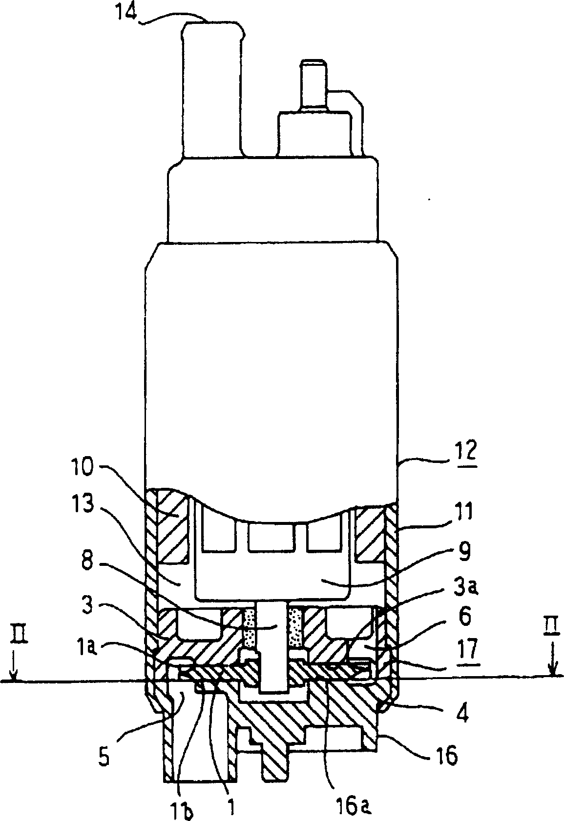
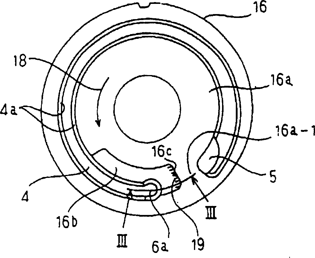
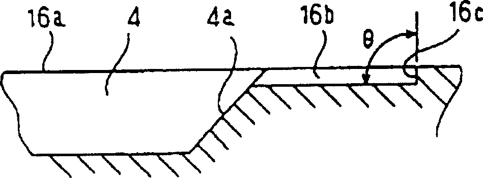
[0033] figure 1 It is a partially cutaway side view showing the electric fuel pump according to Embodiment 1 of the present invention. figure 2 is along figure 1 Sectional view of the pump cover seen on line II-II. image 3 is along figure 2 Enlarged cross-sectional view of line III-III. Figure 4 It is an explanatory diagram showing the effect of the stepped side wall of the pump cover. In the figure, 1, 1a, 3, 4 to 6, 6a, 8 to 14 are the same as the above-mentioned conventional devices, and their descriptions are omitted.
[0034] 16 is a pump cover, which has a sliding surface 16a facing one side surface 1b of the impeller 1 with a slight gap and supporting the impeller 1 . In the vicinity of the side 6a of the sliding surface 16a opposite to the pump chamber outlet 6, a gap that communicates with the inner side wall 4a on the inner peripheral side of the pump chamber 4 and is larger than the small gap between the impeller 1 and the sliding surface 16a is formed. ...
Embodiment 2
[0040] Figure 5 It is a plan view showing a pump cover according to Embodiment 2 of the present invention. Figure 6 is along Figure 5 The enlarged sectional view of line VI-VI in the center. Figure 7 is along Figure 5 The enlarged cross-sectional view of line VII-VII in the middle. In the figure, 4, 5, 6a, 16, 16a, 18 are the same as those in Embodiment 1, and their descriptions are omitted.
[0041] In the vicinity of the side 6a of the sliding surface 16a of the pump cover 16 constituting the pump casing 17, which is opposite to the pump chamber outlet 6, a small gap is formed which communicates with the inner side wall 4a on the inner peripheral side of the pump chamber 4 and is smaller than the impeller 1 and the sliding surface 16a. Larger gap, so that the gap is made as the contact relief portion 20 opposite to the impeller 1, at the end 21 of the contact relief portion 20, that is, at the position opposite to the rotation direction 18 of the impeller 1 ( Figu...
Embodiment 3
[0044] Figure 8 It is a plan view showing a pump cover according to Embodiment 2 of the present invention. Figure 9 is along Figure 8 Enlarged cross-sectional view of the line IX-IX in the middle. In the figure, 4, 5, 6a, 16, 16a, 16b, 16c, 18, and 19 are the same as those in Embodiment 1, and their descriptions are omitted.
[0045] On the sliding surface 16a of the pump cover 16 constituting the pump casing 17, in addition to the contact relief portion 16b shown in Embodiment 1, an inner portion on the inner peripheral side of the pump chamber 4 is formed in the vicinity of the fuel suction port 5 of the sliding surface 16a. The side wall 4a communicates with the gap portion 30 that is larger than the tiny gap between the impeller 1 and the sliding surface 16a. At the downstream end portion 31 of the fuel flow direction of the starting end portion 4b of the pump chamber 4 of the gap portion 30, that is, between the impeller and the impeller. 1 rotation direction 18 rel...
PUM
 Abstract
Description
Claims
Application Information
 - R&D
- Intellectual Property
- Life Sciences
- Materials
- Tech Scout
- Unparalleled Data Quality
- Higher Quality Content
- 60% Fewer Hallucinations
Browse by: Latest US Patents, China's latest patents, Technical Efficacy Thesaurus, Application Domain, Technology Topic, Popular Technical Reports.
© 2025 PatSnap. All rights reserved.Legal|Privacy policy|Modern Slavery Act Transparency Statement|Sitemap|About US| Contact US: help@patsnap.com