Mixing drum abrasion loss prediction method and device thereof and readable storage medium

A prediction method and mixing drum technology, applied in the field of measurement, can solve problems such as low improvement efficiency and inability to accurately predict the effect

Pending Publication Date: 2021-04-23
SANY SPECIAL PURPOSE VEHICLE CO LTD
View PDF8 Cites 3 Cited by
  • Summary
  • Abstract
  • Description
  • Claims
  • Application Information

AI Technical Summary

Problems solved by technology

The efficiency of improving the process parameters of the mixing drum based on experience alone is low, and the effect cannot be accurately predicted
At present, there is no such method that can predict the wear resistance of the mixing drum

Method used


Image

  • Mixing drum abrasion loss prediction method and device thereof and readable storage medium
  • Mixing drum abrasion loss prediction method and device thereof and readable storage medium
  • Mixing drum abrasion loss prediction method and device thereof and readable storage medium

Examples


Embodiment 1

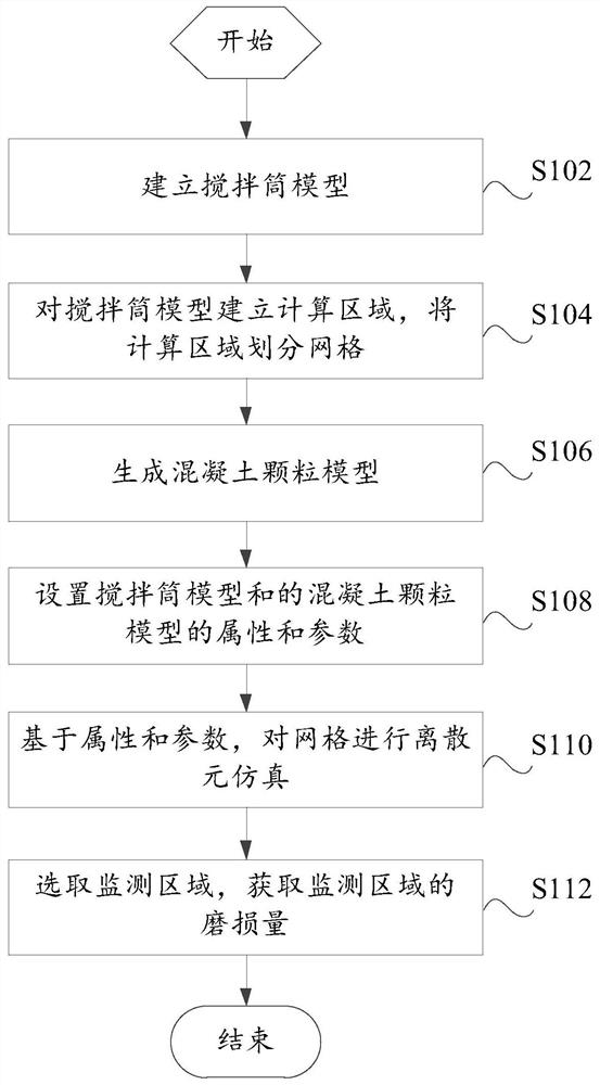
[0061] Such as figure 1 As shown, the present embodiment provides a method for predicting the amount of wear of the mixing drum, comprising the following steps:

[0062] Step S102, establishing a mixing drum model;

[0063] Step S104, establishing a calculation area for the mixing drum model, and dividing the calculation area into grids;

[0064] Step S106, generating a concrete particle model;

[0065] Step S108, setting the attributes and parameters of the mixing drum model and the concrete particle model;

[0066] Step S110, based on attributes and parameters, perform discrete element simulation on the grid;

[0067] Step S112, selecting a monitoring area, and obtaining the wear amount of the monitoring area.

[0068] In the existing technology, the concrete is centralized mixing and supplied on demand. The concrete is produced by the mixing station and then transported to the destination by the concrete truck. The service life of the mixing drum is affected by the wear...

Embodiment 2

[0072] Such as figure 2 As shown, this embodiment provides a method for predicting the amount of wear of the mixing drum. In addition to the technical features of the above-mentioned embodiments, this embodiment further includes the following technical features:

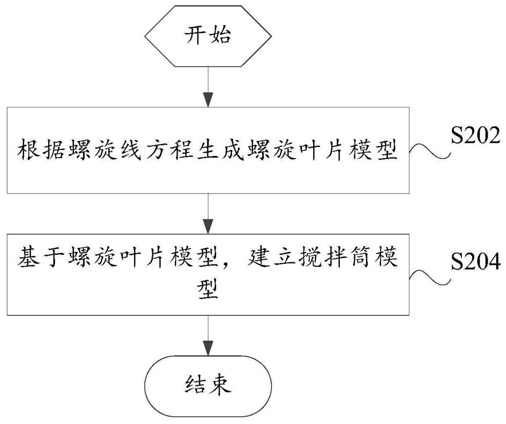
[0073] Establish a mixing drum model, specifically including the following steps:

[0074] Step S202, generating a helical blade model according to the helix equation;

[0075] Step S204, establishing a mixing drum model based on the helical blade model.

[0076] In this embodiment, the helical blade model is generated based on the helical line equation, and then the mixing drum model is obtained. The setting process is simple and conforms to the characteristics of the mixing drum.

Embodiment 3

[0078] Such as image 3 As shown, this embodiment provides a method for predicting the amount of wear of the mixing drum. In addition to the technical features of the above-mentioned embodiments, this embodiment further includes the following technical features:

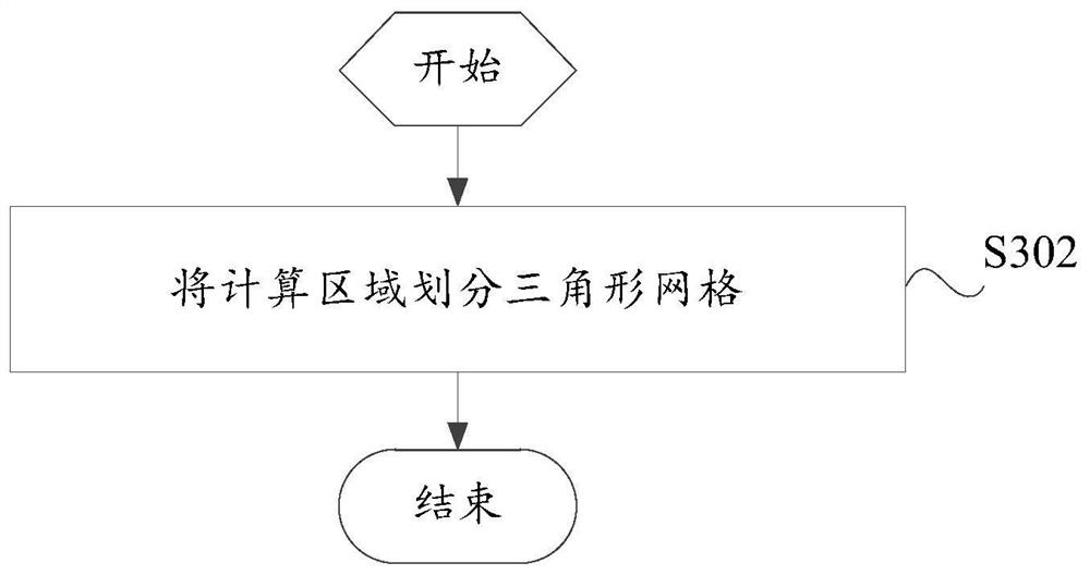
[0079] Divide the calculation area into grids, including:

[0080] Step S302, dividing the calculation area into triangular meshes.

[0081] The grid can be a triangular grid, a rectangular grid, etc. In this embodiment, the calculation area is divided into a triangular grid, so that the model can achieve a better simulation effect.


PUM


Abstract

The invention provides a method and device for predicting the abrasion loss of a mixing drum and a readable storage medium. The mixing drum abrasion loss prediction method comprises the following steps: establishing a mixing drum model; establishing a calculation area for the mixing drum model, and dividing the calculation area into grids; generating a concrete particle model; setting attributes and parameters of the mixing drum model and the concrete particle model; based on the attributes and the parameters, performing discrete element simulation on the grids; selecting a monitoring area, and obtaining the abrasion loss of the monitoring area. In the technical scheme of the invention, the wear condition of the mixing drum is predicted by adopting a discrete element simulation method, the calculation speed is high, the setting is simple and convenient, the time and labor are saved, and the wear condition of the mixing drum can be predicted in advance.

Description

technical field [0001] The invention relates to the field of measurement technology, in particular to a method, device and readable storage medium for predicting the amount of wear of a mixing drum. Background technique [0002] At present, concrete is widely used in daily life and production. With the development of concrete production and wide application, the method of centralized concrete mixing and on-demand supply has gradually formed. Concrete is produced by mixing plants and then transported to various places by concrete trucks. [0003] The wear resistance of the mixing drum determines its service life to a large extent. When a certain part first wears out and fails, the mixing drum must be stopped for maintenance. It is inefficient to improve the process parameters of the mixing drum only based on experience, and the effect cannot be accurately predicted. At present, there is no such method that can predict the wear resistance of the mixing drum. Contents of th...

Claims


Application Information

Patent Timeline
Patent Type & Authority Applications(China)
IPC IPC(8): G06F30/23G06F119/14
CPCG06F30/23G06F2119/14
Inventor 何恒祥姜胜强王志兵
Owner SANY SPECIAL PURPOSE VEHICLE CO LTD
Why Eureka
Try Eureka