
A mechanical seal auxiliary assembly device

An auxiliary assembly device and mechanical seal technology, which is applied in the direction of mechanical equipment, workpiece clamping device, engine components, etc., can solve the problems of increased manpower consumption, springs tend to be biased towards the surroundings, and affect assembly work, so as to avoid manual re-operation , reduce manpower consumption, and avoid the effect of deviation

Active Publication Date: 2022-04-29
丹东盛欣石化设备制造有限公司
View PDF0 Cites 0 Cited by
  • Summary
  • Abstract
  • Description
  • Claims
  • Application Information

AI Technical Summary

Problems solved by technology

[0003] However, at present, when assembling mechanical seals, due to the large strength of the compensation spring, it is very inconvenient to install fasteners such as bolts, and special operators are often required to compress the springs, which increases manpower consumption ;Furthermore, when the compensation spring is compressed, if the force on the spring is not completely vertical, the spring will easily deviate towards the surroundings, which will drive the mechanical seal to deviate and affect the assembly work; in addition, the mechanical seal before and after assembly According to actual needs, a certain amount of lubricating fluid is often used for lubrication. The traditional method requires the use of another lubricating device, which increases the operation steps and is even more inconvenient.

Method used


Image

  • A mechanical seal auxiliary assembly device
  • A mechanical seal auxiliary assembly device
  • A mechanical seal auxiliary assembly device

Examples


Embodiment Construction

[0023] In order to make the technical means, creative features, goals and effects achieved by the present invention easy to understand, the present invention will be further described below in conjunction with specific embodiments.

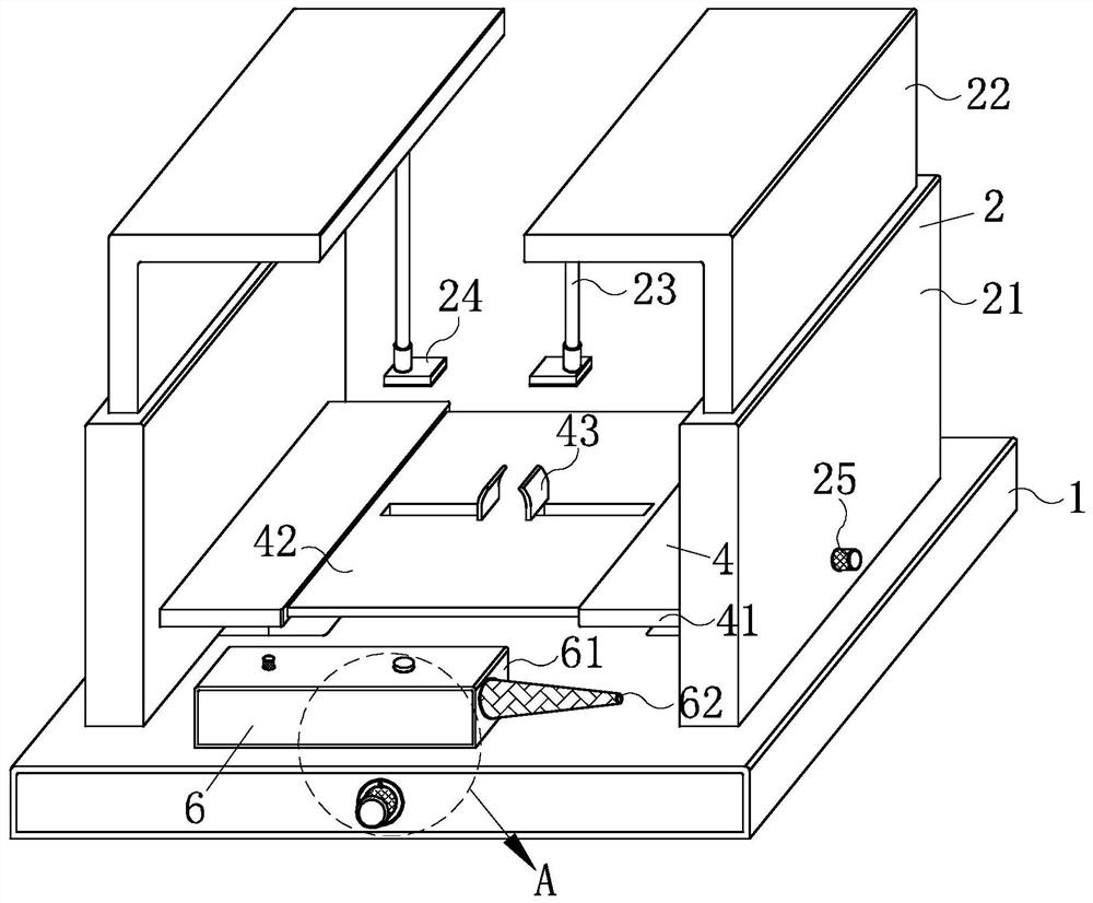
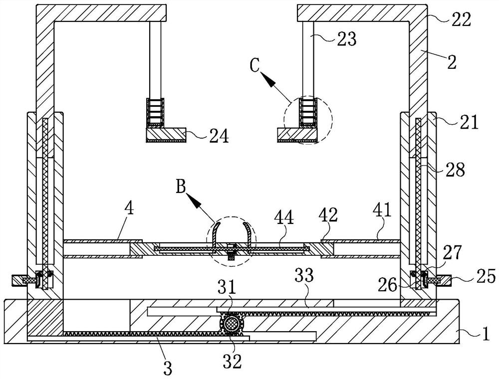
[0024] Such as Figure 1-Figure 6 As shown, a mechanical seal auxiliary assembly device according to the present invention includes a bottom plate 1, a clamping mechanism 2, a movable mechanism 3, a limit mechanism 4, an adjusting mechanism 5 and a lubricating mechanism 6, which are used to fix and place the described The top of the bottom plate 1 is provided with the clamping mechanism 2 that is convenient for clamping and fixing the mechanical seal during actual assembly, and the interior of the bottom plate 1 is provided with a convenient moving adjustment for the clamping mechanism 2. The movable mechanism 3, the clamping mechanism 2 is provided with the limiting mechanism 4 which is convenient for fixing and limiting the mechanical seal in th...


PUM


Abstract

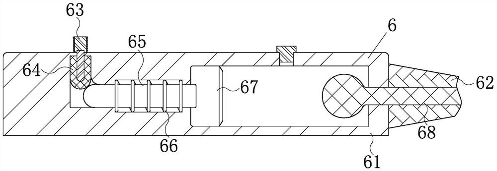
The invention relates to the technical field of mechanical assembly, in particular to an auxiliary assembly device for mechanical seals, including a bottom plate, a clamping mechanism, a movable mechanism, a limit mechanism, an adjustment mechanism and a lubricating mechanism; when in use, the clamping mechanism is set on the bottom plate The top of the top, so that it is convenient to directly press the compensation spring on the mechanical seal during actual operation, avoiding manual re-operation and reducing manpower consumption; the limit mechanism is set on the inner side of the clamping mechanism, through the corresponding screw drive and The support plate assembly, so that it can exert a horizontal limiting force on the mechanical seal during use, thereby avoiding the offset of the compensation spring, and finally ensuring accurate positioning of the mechanical seal and normal assembly work; the lubrication mechanism It is located on one side of the top of the bottom plate, through the corresponding storage component and the spring block component, so as to facilitate the lubrication of the mechanical seal at any time during actual operation, avoiding the use of other lubrication equipment.

Description

technical field [0001] The invention relates to the technical field of mechanical assembly, in particular to a mechanical seal auxiliary assembly device. Background technique [0002] A mechanical seal refers to a device that prevents fluid leakage by at least one pair of end faces perpendicular to the axis of rotation, under the action of fluid pressure and the elastic force (or magnetic force) of the compensation mechanism, and the cooperation of auxiliary seals to keep fit and slide relative to each other. A mechanical seal is a shaft seal device for a rotating machine. Such as centrifugal pumps, centrifuges, reactors and compressors and other equipment. "Mechanical seal" is often referred to as "mechanical seal" for short, and has a wide range of applications in industry. [0003] However, at present, when assembling mechanical seals, due to the large strength of the compensation spring, it is very inconvenient to install fasteners such as bolts, and special operators ...

Claims


Application Information

Patent Timeline
Patent Type & Authority Patents(China)
IPC IPC(8): B25B11/02F16N7/12F16N7/14
CPCB25B11/02F16N7/12F16N7/14
Inventor 郁佳杰薛宇峰张天宇
Owner 丹东盛欣石化设备制造有限公司
Learn More