A feeding mechanical arm of a mechanical arm device
What is AI technical title?
AI technical title is built by Patsnap AI team. It summarizes the technical point description of the patent document.
A mechanical arm and manipulator technology, applied in the field of robots, can solve the problems of unfavorable production efficiency, high labor cost, time-consuming and labor-intensive, etc., and achieve the effect of saving manpower, ensuring stability, and improving production efficiency.
Inactive Publication Date: 2021-06-15
HUNAN MECHANICAL & ELECTRICAL POLYTECHNIC
View PDF5 Cites 2 Cited by
Summary
Abstract
Description
Claims
Application Information
AI Technical Summary
This helps you quickly interpret patents by identifying the three key elements:
Problems solved by technology
Method used
Benefits of technology
Problems solved by technology
[0002] Now in the process of product processing in the engineering industry, construction industry, chemical industry, etc., the products need to go through multiple processes to complete the processing, and when processing from the previous process to the next process, it is often necessary to complete the transfer or handling of the product to be formed. At present, manual transfer or handling is generally used, which has high labor costs, time-consuming and laborious, and is not conducive to the improvement of production efficiency. At the same time, manual handling has potential safety hazards.
Method used
Image
Click on the blue label to locate the original text in one second.
Reading with bidirectional positioning of images and text.
Examples
Embodiment Construction
[0027] In order to enable those skilled in the art to better understand the technical solution of the present invention, the present invention will be described in detail below in conjunction with the accompanying drawings. The description in this part is only exemplary and explanatory, and should not have any limiting effect on the protection scope of the present invention. . It should be noted that like numerals and letters denote similar items in the following figures, therefore, once an item is defined in one figure, it does not require further definition and explanation in subsequent figures.
[0028] It should be noted that the orientation or positional relationship indicated by the terms "center", "upper", "lower", "left", "right", "vertical", "horizontal", "inner" and "outer" are Based on the orientation or positional relationship shown in the drawings, or the orientation or positional relationship that the inventive product is usually placed in use, it is only for the...
PUM
Abstract
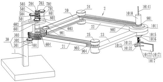
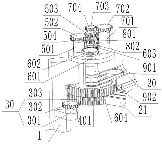
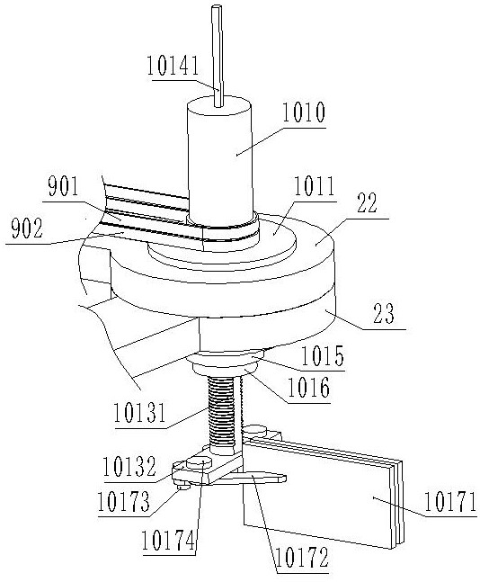
The invention discloses a material-discharging mechanical arm of a manipulator device, which includes a frame, a mechanical arm, a clamping mechanism, and a total power drive mechanism. The total power drive mechanism includes a first rotation drive assembly, a second rotation drive assembly, a third rotation drive assembly, and a The drive assembly, the fourth rotation drive assembly, the first transmission assembly, the second transmission assembly, and the third transmission assembly, the clamping mechanism includes a clamping finger, a first clamping link, a second clamping link, and a lifting bracket , a first rotary cylinder, a second rotary cylinder, and a nut sleeve, the first rotary drive assembly, the second rotary drive assembly, the third rotary drive assembly, and the fourth rotary drive assembly are installed above the frame , one end of the mechanical arm is rotatably connected to the upper part of the frame, and one end of the mechanical arm is connected to the first rotary drive assembly. The invention has a stable and reliable structure, realizes automatic transfer or handling of objects without manual participation, saves labor costs, and improves production efficiency.
Description
technical field [0001] The invention relates to the technical field of robots, in particular to a feeding robot arm of a robot device. Background technique [0002] Now in the process of product processing in the engineering industry, construction industry, chemical industry, etc., the products need to go through multiple processes to complete the processing, and when processing from the previous process to the next process, it is often necessary to complete the transfer or handling of the product to be formed. At present, manual transfer or handling is generally used, which has high labor costs, time-consuming and laborious, and is not conducive to the improvement of production efficiency. At the same time, manual handling has potential safety hazards. Contents of the invention [0003] The purpose of the present invention is to overcome the deficiencies of the prior art and provide a mechanical arm for discharging materials. The structure of the present invention is stab...
Claims
Application Information
Patent Timeline
Application Date:The date an application was filed.
Publication Date:The date a patent or application was officially published.
First Publication Date:The earliest publication date of a patent with the same application number.
Issue Date:Publication date of the patent grant document.
PCT Entry Date:The Entry date of PCT National Phase.
Estimated Expiry Date:The statutory expiry date of a patent right according to the Patent Law, and it is the longest term of protection that the patent right can achieve without the termination of the patent right due to other reasons(Term extension factor has been taken into account ).
Invalid Date:Actual expiry date is based on effective date or publication date of legal transaction data of invalid patent.

