Equipment for wood pile cutting
A technology for equipment and wood piles, applied in the field of wood pile cutting equipment, can solve the problems of low machine flexibility and low processing efficiency.
- Summary
- Abstract
- Description
- Claims
- Application Information
AI Technical Summary
Problems solved by technology
Method used
Image

Examples
Embodiment 1
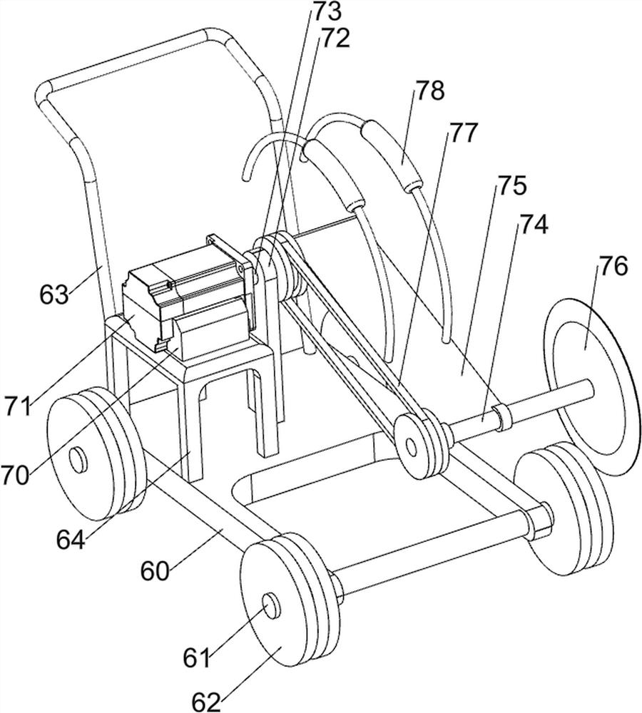
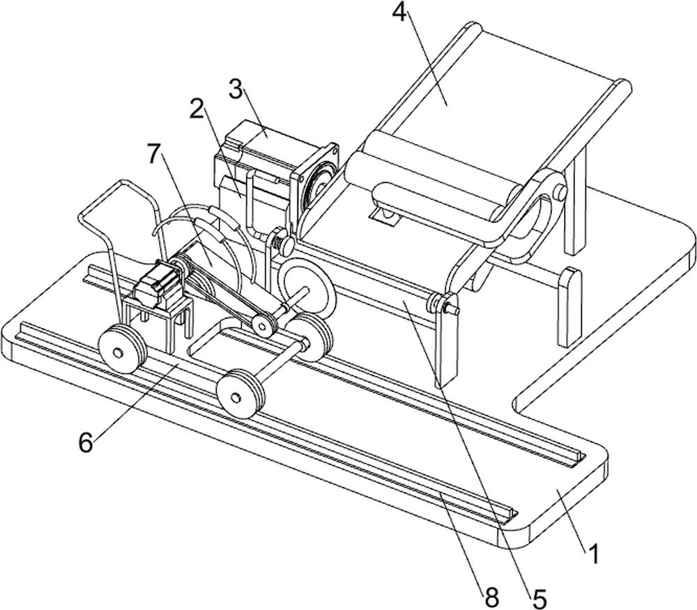
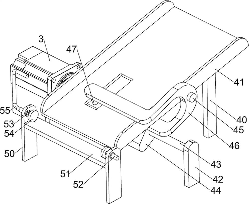
[0021] A device for cutting stakes such as Figure 1-3 As shown, it includes a bottom plate 1, a fixed seat 2, a first servo motor 3, a feeding mechanism 4, a placement mechanism 5, a moving mechanism 6 and a cutting mechanism 7. The left side of the top of the bottom plate 1 is provided with a fixed seat 2. A first servo motor 3 is provided, a blanking mechanism 4 is provided on the rear side of the top of the bottom plate 1, a placing mechanism 5 is provided on the top middle of the bottom plate 1, a moving mechanism 6 is placed on the front side of the top of the bottom plate 1, and a cutting mechanism 7 is arranged inside the moving mechanism 6 .
[0022] The staff places the wooden piles in the blanking mechanism 4, and then starts the first servo motor 3 to work, the first servo motor 3 drives the blanking mechanism 4 to work, and the blanking mechanism 4 drives the wooden piles to carry out intermittent blanking one by one, and the blanked wood The pile moves into the ...
PUM
 Abstract
Description
Claims
Application Information