
Installation structure of differential and driven bevel gear

A technology of installation structure and differential, which is applied in the direction of differential transmission, transmission, transmission parts, etc., can solve the problems of affecting transmission efficiency and complicated process structure, and achieve the goal of improving transmission efficiency, reducing costs and reducing weight Effect

Pending Publication Date: 2021-04-30
LIUZHOU WULING MOTORS +1
View PDF0 Cites 1 Cited by
  • Summary
  • Abstract
  • Description
  • Claims
  • Application Information

AI Technical Summary

Problems solved by technology

[0003] The purpose of the present invention is to provide an installation structure of a differential gear and a driven bevel gear, aiming to solve the problems of the bolt connection method in the prior art with complex process structure and affecting transmission efficiency

Method used


Image

  • Installation structure of differential and driven bevel gear
  • Installation structure of differential and driven bevel gear
  • Installation structure of differential and driven bevel gear

Examples


Embodiment Construction

[0017] In order to make the objectives, technical solutions and advantages of the present invention clearer, the present invention will be further described in detail below with reference to the accompanying drawings through specific embodiments. It should be understood that the specific embodiments described herein are only used to explain the present invention, but not to limit the present invention.

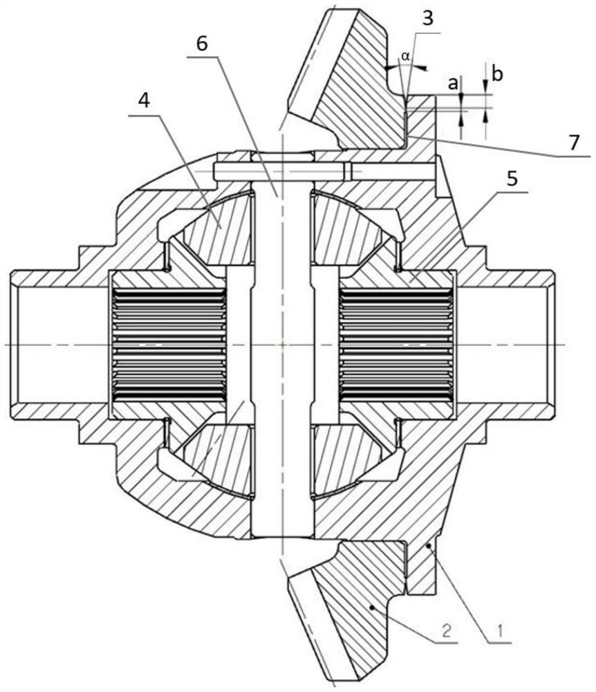
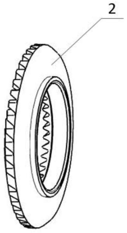
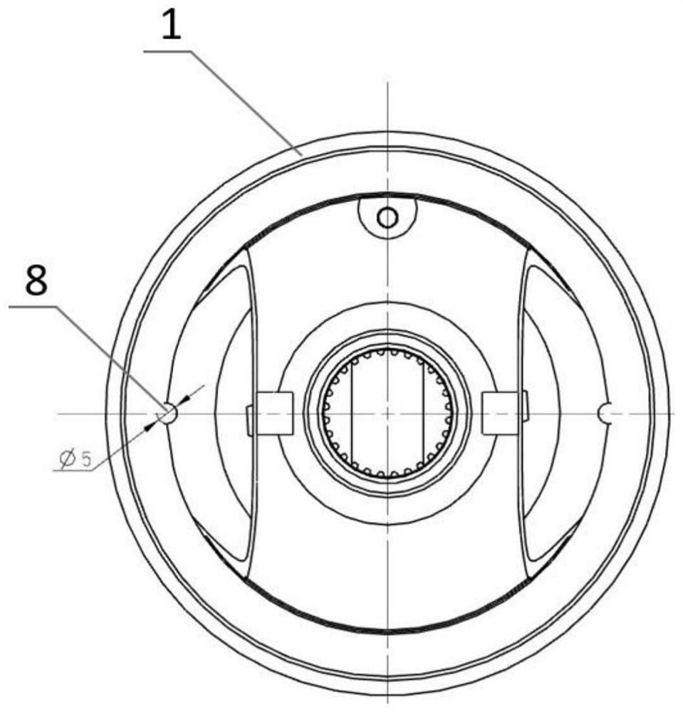
[0018] The embodiment of the present invention provides an installation structure of a differential gear and a driven bevel gear, such as figure 1 As shown, the differential includes a differential housing 1, a planetary shaft 6, a planetary gear 4 and a side gear 5. The differential housing 1 is provided with a cavity inside, and the planetary gear 4 and the side gear 5 are located in the cavity Among them, the upper and lower sides of the differential housing 1 are provided with planetary shaft holes that communicate with the cavity, the planetary shaft 6 is arranged in the ...


PUM


Abstract

The invention provides an installation structure of a differential and a driven bevel gear. The differential comprises a differential shell, a planet shaft, a planet gear and a half shaft gear, the differential shell is internally provided with a cavity, and the planet gear and the half shaft gear are located in the cavity; and the driven bevel gear is arranged on the differential shell in a sleeving mode and is in interference fit with the differential shell, a welding groove with the angle being alpha is formed in the attaching face of the driven bevel gear and the differential shell, the driven bevel gear and the differential shell are welded and fixed at the welding groove, and an exhaust groove is formed below the welding groove. According to the installation structure of the differential and the driven bevel gear, a bolt hole structure of the driven bevel gear is omitted, the drilling procedure is omitted, the beat is improved, the tooth thickness is reduced, the weight is reduced, and cost is reduced; bolt holes and reinforcing ribs of the differential shell are omitted, the drilling procedure is omitted, the weight is reduced, and cost is reduced; and due to the fact that resistance of the reinforcing ribs and the bolts does not exist, transmission efficiency is improved.

Description

technical field [0001] The invention belongs to the technical field of transmission devices, and in particular relates to an installation structure of a differential gear and a passive bevel gear. Background technique [0002] During the driving process of the car, the main reducer and the differential transmit the main torque, the torque is transmitted from the engine, transmitted to the main reducer through the transmission shaft, and the differential is driven by the driving bevel gear and the tooth surface of the bevel gear. , half shaft and wheels rotate to realize torque transmission; the passive bevel gear drives the differential to rotate through the connection with the differential case to realize torque transmission. The connection between the gear teeth and the differential is the key to affecting torque transmission and transmission efficiency. At present, the connection between the passive bevel gear and the differential case is bolted. The passive bevel gear ...

Claims


Application Information

Patent Timeline
Patent Type & Authority Applications(China)
IPC IPC(8): F16H48/38F16H48/40F16H57/023F16H48/08
CPCF16H48/08F16H48/38F16H48/40F16H57/023F16H2048/385
Inventor 黄荣国莫伟忠陈祖建莫淑君玉勇志
Owner LIUZHOU WULING MOTORS
Learn More