
Device for metal material strip automatic feeding welding

A technology of automatic feeding and metal strips, applied in welding equipment, laser welding equipment, metal processing equipment, etc., can solve the problems of high product defect rate, inaccurate welding positioning, poor stability, etc., to reduce processing and procurement costs. , fast tempo, good stability

Inactive Publication Date: 2019-06-07
SHANGHAI SHARETEK TECH CO LTD
View PDF15 Cites 7 Cited by
  • Summary
  • Abstract
  • Description
  • Claims
  • Application Information

AI Technical Summary

Problems solved by technology

[0003] Electronic communication products often use welding parts with small size, high precision, large batches and short production cycle. Such parts are usually welded by laser welding machines. The yield rate of the product is high, and the equipment is stable and reliable; at present, the production equipment generally has the disadvantages of slow tempo, inaccurate welding positioning, high defective rate of products after welding, and poor stability

Method used


Image

  • Device for metal material strip automatic feeding welding
  • Device for metal material strip automatic feeding welding
  • Device for metal material strip automatic feeding welding

Examples


Embodiment 1

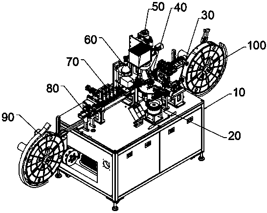
[0029] see figure 1 , in the embodiment of the present invention, a kind of equipment that is used for the automatic feeding welding of metal strip, comprises frame part 10, and nut vibrating plate feeding part 20 is installed on described frame part 10, and nut vibrating plate feeding part A nut feeding mechanism 30 is installed on the side of 20, a station turntable mechanism 40 is installed on the frame part 10 inside the nut feeding mechanism 30, and a welding jig is installed on the frame part 10 inside the station turntable mechanism 40. Mechanism 50, a laser welding head is installed on the upper end of the welding jig mechanism 50, an image detection mechanism 60 is installed on the side of the welding jig mechanism 50, and an unwinding mechanism 100 is installed on the other side of the welding jig mechanism 50. A defective product marking mechanism 70 is installed on the side of the detection mechanism 60 , a material tape feeding mechanism 80 is installed on the sid...

Embodiment 2

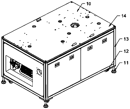
[0032] A kind of equipment for automatic feeding and welding of metal strips, please refer to figure 2 , the embodiment of the present invention is further defined on the basis of embodiment 1.

[0033] Further, the frame part 10 is provided with a square steel welding frame 13, and the bottom of the square steel welding frame 13 is fixed with an array of supporting cups 11 and casters 12, and the square steel welding frame 13 is surrounded by outer cover doors. , The top of the square steel welding frame 13 is provided with a table panel 14 .

Embodiment 3

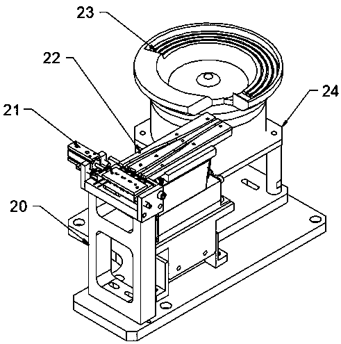
[0035] A kind of equipment for automatic feeding and welding of metal strips, please refer to image 3 , the embodiment of the present invention is further defined on the basis of embodiment 1.

[0036] Further, the nut vibrating plate feeding part 20 is provided with a vibrating plate 23, the vibrating plate 23 is fixed by a vibrating plate mounting frame 24, a linear vibrating track 22 is installed on the side of the vibrating plate 23, and the side of the linear vibrating track 22 Cylinder 21 is installed on the limit.


PUM


Abstract

The invention relates to a metal material strip welding device, in particular to a device for metal material strip automatic feeding welding. The device for metal material strip automatic feeding welding comprises a rack component, a nut vibrating plate feeding component is mounted on the rack component, a nut feeding mechanism is mounted on the side edge of the nut vibrating plate feeding component, a station turntable mechanism is mounted on the inner side of the nut feeding mechanism, a welding jig mechanism is mounted on the inner side of the station turntable mechanism, an image detectionmechanism is mounted on the side edge of the welding jig mechanism, an unwinding mechanism, a defective product neaten mechanism, and a material strip feeding mechanism are mounted on the other sideedgeof the welding jig mechanism, and a winding mechanism is mounted on the side wall of the rack component. According to the device for metal material strip automatic feeding welding, the takt is high, the defect rate is low, and the stability is good; the device for metal material strip automatic feeding welding has the simple structure, the low manufacturing cost, and high cost performance; andthe disadvantages of low takt, inaccurate welding positioning, high defect rate after welding and poor stability generallyexisting inan existing production device areovercome.

Description

technical field [0001] The invention relates to a welding equipment for metal strips, in particular to an equipment for automatic feeding and welding of metal strips. Background technique [0002] Electronic products are related products based on electric energy, mainly including: watches, smart phones, telephones, televisions, video disc players (VCD, SVCD, DVD), video recorders, camcorders, radios, tape recorders, combined speakers, CD players (CD), computers, mobile communication products, etc. Because the early products were mainly based on electronic tubes, they were named electronic products. [0003] Electronic communication products often use welding parts with small size, high precision, large batches and short production cycle. Such parts are usually welded by laser welding machines. The yield rate of the product is high, and the equipment is stable and reliable; at present, the production equipment generally has the disadvantages of slow tempo, inaccurate weldin...

Claims


Application Information

Patent Timeline
Patent Type & Authority Applications(China)
IPC IPC(8): B23K26/21B23K26/70
Inventor 陈远明丁垒廖超邓天桥张高华
Owner SHANGHAI SHARETEK TECH CO LTD
Learn More