
Magnetic liquid seal

A magnetic liquid and sealing device technology, applied in the direction of engine sealing, mechanical equipment, engine components, etc., can solve the problems of magnetic liquid loss, affecting sealing performance, small sealing gap, etc., to achieve the effect of not easy adsorption and uniform distribution

Active Publication Date: 2022-04-12
TSINGHUA UNIV
View PDF5 Cites 0 Cited by
  • Summary
  • Abstract
  • Description
  • Claims
  • Application Information

AI Technical Summary

Problems solved by technology

However, due to the small sealing gap and the response characteristics of the magnetic liquid to the magnetic field, it is a difficult problem to fill the magnetic liquid into the sealing gap uniformly and effectively to form a stable and ideal magnetic liquid seal.
In addition, the magnetic liquid is easily absorbed by the permanent magnet during the filling process, resulting in the loss of the magnetic liquid and affecting the sealing performance

Method used


Image

  • Magnetic liquid seal
  • Magnetic liquid seal
  • Magnetic liquid seal

Examples


Embodiment 1

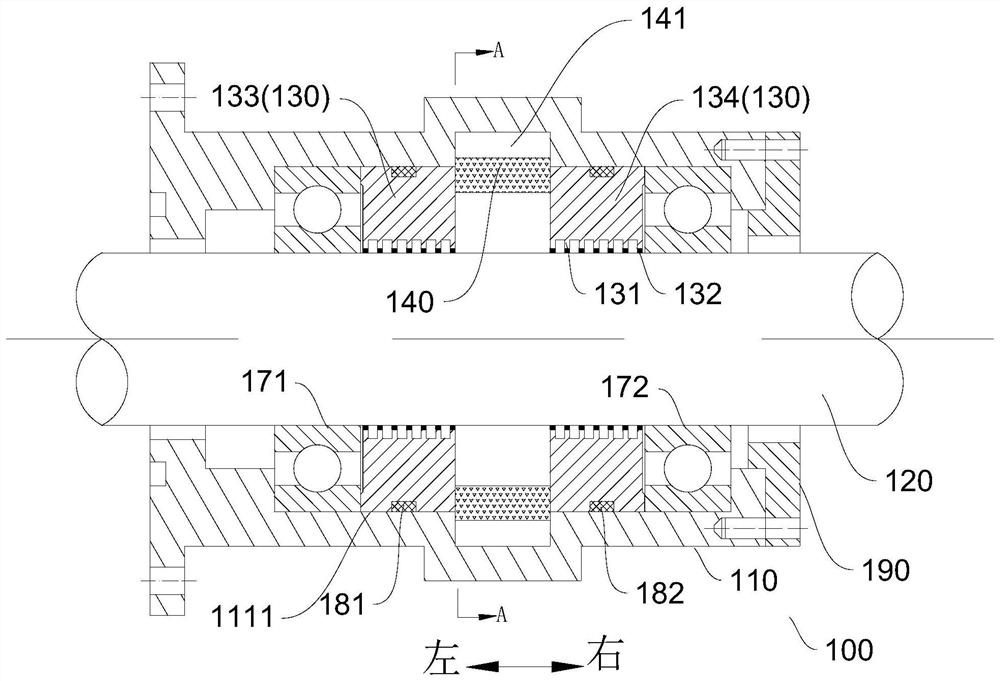
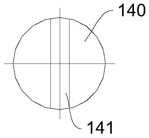
[0046] Such as figure 1 As shown, the magnetic liquid sealing device 100 in this embodiment includes a shaft housing 110 , a rotating shaft 120 , a first pole piece 133 , a second pole piece 134 and a permanent magnet set (first permanent magnet set). The first permanent magnet group includes several permanent magnets 140 arranged around the rotating shaft 120 along the circumferential direction of the rotating shaft 120 . In this embodiment, the permanent magnet 140 is cylindrical, and its axial direction is the same as that of the rotating shaft 120 . It can be understood that, in other embodiments, the permanent magnet 140 may have other columnar structures.

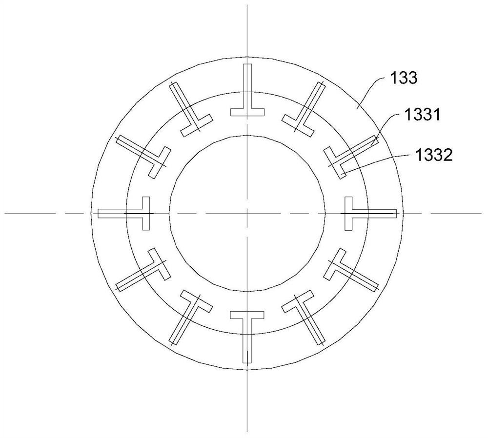
[0047] Both the first pole piece 133 and the second pole piece 134 are sheathed on the rotating shaft 120 , and their outer peripheral surfaces are connected to the peripheral wall surface 1111 of the chamber 111 so as to be connected to the shaft housing 110 . The first permanent magnet group is located between the...

Embodiment 2

[0065] The structure of the magnetic liquid sealing device in this embodiment is basically the same as that in Embodiment 1, and will not be repeated here. The difference is that a number of avoidance grooves 112 are formed on the peripheral wall surface 1111, and the number of escape grooves 112 correspond to the number of permanent magnets 140 in the first permanent magnet group. Opposite upward, that is, at least a part of the permanent magnet 140 may be located in the avoidance groove 112 corresponding thereto. It can be understood that, the plurality of escape grooves 112 are arranged around the circumference of the rotating shaft 120 on the peripheral wall surface 1111 . Alternatively, in other embodiments, a plurality of escape grooves 112 arranged in a circumferential direction around the rotating shaft 120 are formed on the peripheral wall surface 1111 , and each escape groove 112 corresponds to a plurality of permanent magnets 140 .

[0066] It should be noted that,...

Embodiment 3

[0068] The structure of the magnetic liquid sealing device in this embodiment is basically the same as that in Embodiment 1, and will not be repeated here. The difference is that if Figure 4 As shown, the axle housing 110 in this embodiment includes a first sub-axle housing 113 and a second sub-axle housing 114 . The first sub-shaft housing 113 and the second sub-shaft housing 114 are arranged in the axial direction of the rotating shaft 120 and are detachably connected to each other. The first sub-axle housing 113 and the second sub-axle housing 114 jointly define a cavity 111 and an escape groove 112 . Optionally, the first sub-axle housing 113 and the second sub-axle housing 114 are connected by connecting bolts 160 .

[0069] The first pole shoe 133 is located in the sub-chamber formed by the first sub-shaft housing 113 , and the second pole shoe 134 is located in the sub-chamber formed by the second sub-shaft housing 114 . The left end of the permanent magnet 140 exte...


PUM


Abstract

Embodiments of the present invention provide a magnetic liquid sealing device and an assembly method thereof. According to the magnetic liquid sealing device of the embodiment of the present invention, an avoidance groove for avoiding the permanent magnet is provided on the peripheral wall of the chamber, and the permanent magnet is located in the avoidance groove and can be further away from the pole teeth, thereby facilitating the adjustment of the permanent magnet and the permanent magnet during the assembly process. The relative distance between the pole teeth enables the magnetic liquid to be evenly and effectively distributed in the sealing gap, and also prevents the magnetic liquid from being mistakenly adsorbed to the permanent magnet. The magnetic liquid sealing device provided by the embodiment of the present invention has the advantages of uniform distribution of the magnetic liquid and difficulty of the magnetic liquid being absorbed by the permanent magnet.

Description

technical field [0001] The invention relates to the field of sealing devices, in particular to a magnetic liquid sealing device. Background technique [0002] The magnetic liquid sealing device has the advantages of zero leakage, no wear, long life, simple structure, etc., and is used by more and more industries. However, due to the small sealing gap and the response characteristics of the magnetic liquid to the magnetic field, it is a difficult problem to fill the magnetic liquid into the sealing gap uniformly and effectively to form a stable and ideal magnetic liquid seal. In addition, the magnetic liquid is easily absorbed by the permanent magnet during the filling process, resulting in the loss of the magnetic liquid and affecting the sealing performance. Contents of the invention [0003] The present invention aims to solve one of the technical problems in the related art at least to a certain extent. For this reason, the embodiment of the present invention proposes...

Claims


Application Information

Patent Timeline
Patent Type & Authority Patents(China)
IPC IPC(8): F16J15/43
CPCF16J15/43
Inventor 李德才赵云翔杨晟
Owner TSINGHUA UNIV
Learn More