Flow velocity monitoring device and flow velocity monitoring method for sewage draining exit flow detection

A technology for monitoring devices and sewage outlets, which is applied in the field of flow rate monitoring devices for flow detection at sewage outlets, can solve the problems of leakage at the installation place of the monitoring device on the sewage pipe, affect the management of the sewage pipe, and difficult installation and operation, and achieve convenient management, The effect of saving time and effort for installation and avoiding leakage

Pending Publication Date: 2021-04-30
TIANJIN ENVIRONMENT MONITORING CENT +1
View PDF11 Cites 1 Cited by
  • Summary
  • Abstract
  • Description
  • Claims
  • Application Information

AI Technical Summary

Problems solved by technology

[0004] The purpose of the present invention is to provide a flow rate monitoring device and monitoring method for sewage outlet flow detection in order to solve the above problems, which solves the difficulty of installation and operation when the current sewage outlet flow monitoring device needs tools or manual support for alignment. Large, time-consuming and labor-intensive, prone to installation deviations, resulting in leakage at the installation of the monitoring device on the sewage pipe, affecting the management of the sewage pipe

Method used


Image

  • Flow velocity monitoring device and flow velocity monitoring method for sewage draining exit flow detection
  • Flow velocity monitoring device and flow velocity monitoring method for sewage draining exit flow detection
  • Flow velocity monitoring device and flow velocity monitoring method for sewage draining exit flow detection

Examples


Embodiment Construction

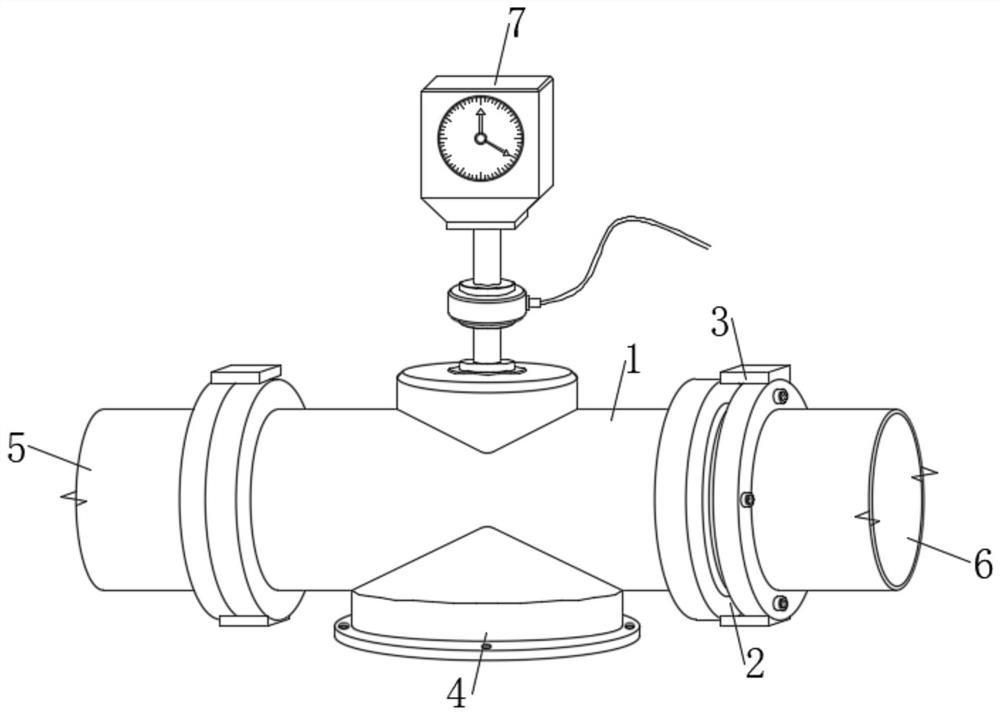
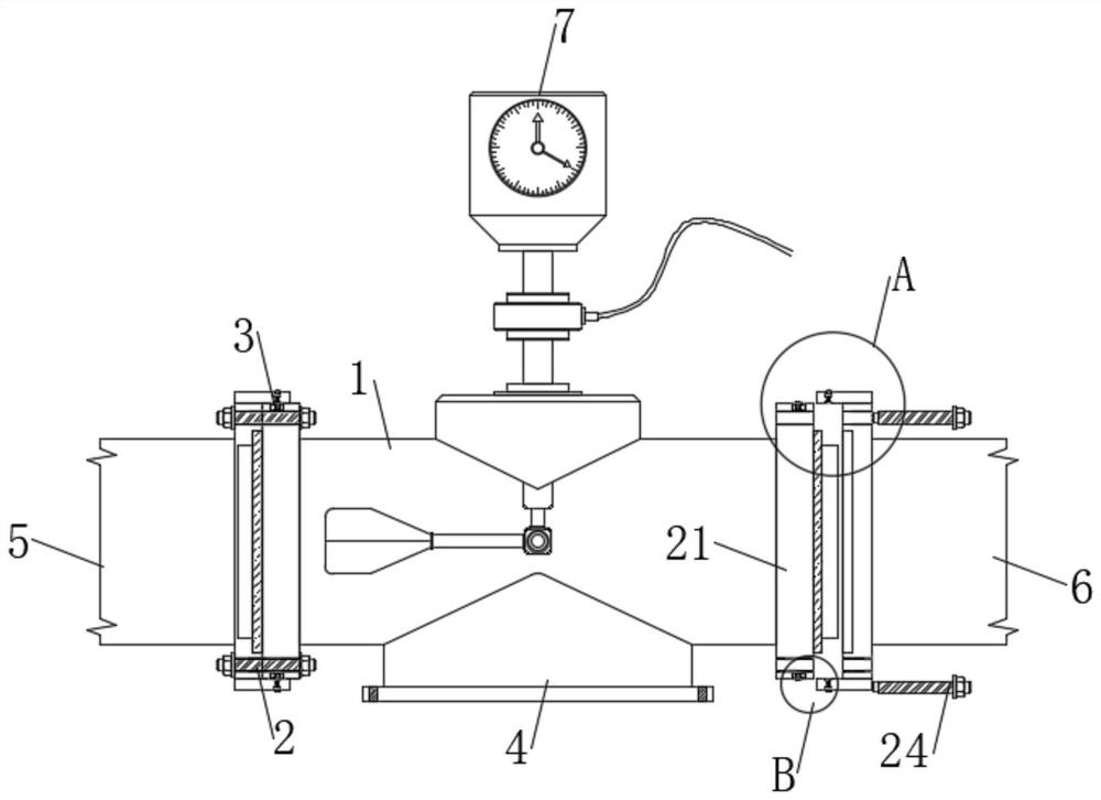
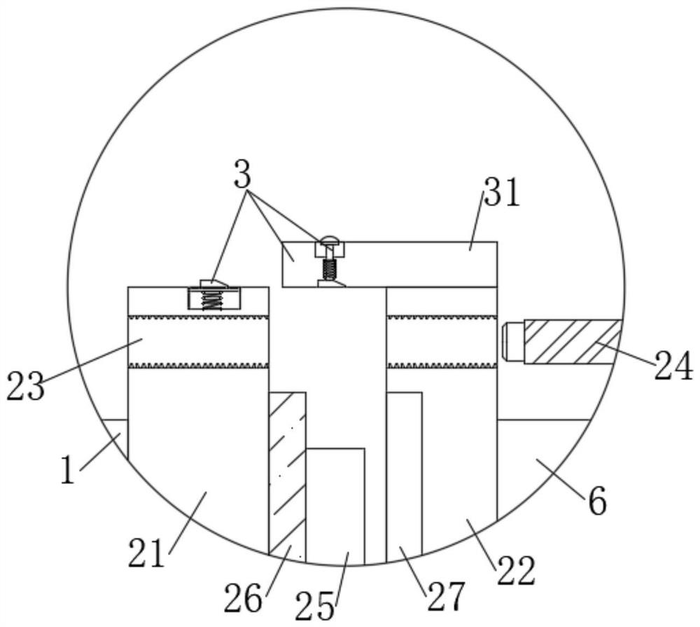
[0032] like Figure 1-8 As shown, this specific embodiment adopts the following technical solutions: a flow rate monitoring device for flow detection of sewage outlets, including a monitoring pipeline 1 and a connecting structure 2, one side of the monitoring pipeline 1 is connected to the No. 1 sewage pipe 5 through the connecting structure 2 Fixed installation, the side of the monitoring pipeline 1 away from the No. 1 sewage pipe 5 is fixedly installed through the connection structure 2 and the No. 2 sewage pipe 6, the connection structure 2 is provided with a positioning mechanism 3, and the bottom of the monitoring pipeline 1 is fixed A support assembly 4 is installed, and the bottom of the monitoring pipeline 1 is fixedly installed on the ground through the support assembly 4 and the sewage pipeline. The side of the monitoring pipeline 1 away from the support assembly 4 is fixedly installed with a flow meter 7, and the flow meter 7 is fixed. The output end is electrically...


PUM


Abstract

The invention discloses a flow velocity monitoring device and flow velocity monitoring method for sewage draining exit flow detection. The device comprises a monitoring pipeline and a connecting structure, one side of the monitoring pipeline is fixedly connected with a first blow-off pipe through the connecting structure, and the side, away from the first blow-off pipe, of the monitoring pipeline is fixedly connected with a second blow-off pipe through the connecting structure; a positioning mechanism is arranged on the connecting structure, a supporting assembly is fixedly installed at the bottom of the monitoring pipeline, the bottom of the monitoring pipeline is fixedly installed on the blow-off pipeline installation ground through the supporting assembly, and a flow meter is fixedly installed on the side, away from the supporting assembly, of the monitoring pipeline. The device and the method have the beneficial effects that remote monitoring and management of the flow velocity of the blow-off outlet of the blow-off pipe are realized, management is convenient and efficient, and installation between a monitoring pipeline and the blow-off pipe is facilitated; time and labor are saved during installation, the installation stability of the monitoring device on the blow-off pipe is guaranteed, the sealing performance of connection between the monitoring pipeline and the blow-off pipe is improved, the leakage phenomenon at the joint of the monitoring device on the blow-off pipe is avoided, and the service life of equipment is prolonged.

Description

Technical field: [0001] The invention belongs to the technical field of flow velocity monitoring, and in particular relates to a flow velocity monitoring device and a monitoring method for flow detection of sewage outlets. Background technique: [0002] A large amount of sewage is produced in daily production and life. During the sewage discharge process, the flow rate of the sewage needs to be monitored. The flow meter, also known as the "velocity meter", is an instrument used to measure the velocity of the fluid in the pipeline. After the flow velocity is measured, it is multiplied by the fluid cross-section to convert it into a flow rate, so it is also used for indirect measurement of flow rate. There are speed measuring tubes, hole flow meters, speed measuring nozzles and Wenchenli flow meters, etc. The flow meter is a kind of open channel flow velocity / flow measurement designed for hydrological monitoring, river flow monitoring, agricultural irrigation, municipal water ...

Claims


Application Information

Patent Timeline
Patent Type & Authority Applications(China)
IPC IPC(8): G01F15/18G01F15/06
CPCG01F15/18G01F15/185G01F15/063G01F15/065
Inventor 王秋莲韩龙夏妍梦张震韩彤付振超杨莹梅鹏蔚
Owner TIANJIN ENVIRONMENT MONITORING CENT
Why Eureka
Try Eureka