Laser path planning visual algorithm
A path planning and vision technology, applied in computing, image data processing, instruments, etc., can solve problems such as insufficient vacancy alignment, low position, incomplete punching, etc., and achieve the effect of rapid positioning and recognition
- Summary
- Abstract
- Description
- Claims
- Application Information
AI Technical Summary
Problems solved by technology
Method used
Image

Examples
Embodiment 1
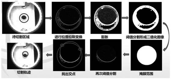
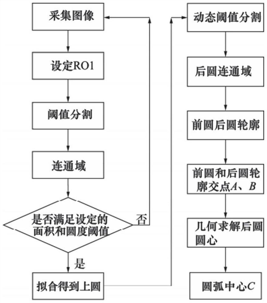
[0039] A laser path planning vision algorithm is characterized in that it comprises the following steps:
[0040] Step ①, first move the lens to ensure that the hole to be cut is within the area; take a photo to obtain the original image;
[0041] In step ②, Laplace transform is performed on the original image to enhance the edge difference of the image;
[0042] Step ③, perform expansion operation to enlarge the edge area;
[0043] Step ④, threshold segmentation, highlight the edge;
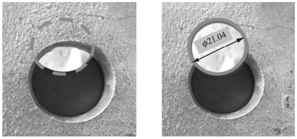
[0044] Step ⑤, find the prototype with the largest area, that is, the hole position of the upper steel plate in reality, and the prototype obtained here is marked as circle R01;
[0045] Step ⑥, based on the hole position found in step ⑤, threshold segmentation is performed on the basis of the Laplace transformed image;
[0046] Step ⑦, find out the contour, and merge similar contours, and finally extract the largest contour;
[0047] In step ⑧, the fitted circle is obtained through the cont...
Embodiment 2
[0057] A laser path planning vision algorithm is characterized in that it comprises the following steps:
[0058] Step ①, first move the lens to ensure that the hole to be cut is within the area; take a photo to obtain the original image;
[0059] In step ②, Laplace transform is performed on the original image to enhance the edge difference of the image;
[0060] Step ③, perform expansion operation to enlarge the edge area;
[0061] Step ④, threshold segmentation, highlight the edge;
[0062] Step ⑤, find the prototype with the largest area, that is, the hole position of the upper steel plate in reality, and the prototype obtained here is marked as circle R01;
[0063] Step ⑥, based on the hole position found in step ⑤, threshold segmentation is performed on the basis of the Laplace transformed image;
[0064] Step ⑦, find out the contour, and merge similar contours, and finally extract the largest contour;
[0065] In step ⑧, the fitted circle is obtained through the cont...
PUM
| Property | Measurement | Unit |
|---|---|---|
| Diameter | aaaaa | aaaaa |
| Diameter | aaaaa | aaaaa |
Abstract
Description
Claims
Application Information
 - Generate Ideas
- Intellectual Property
- Life Sciences
- Materials
- Tech Scout
- Unparalleled Data Quality
- Higher Quality Content
- 60% Fewer Hallucinations
Browse by: Latest US Patents, China's latest patents, Technical Efficacy Thesaurus, Application Domain, Technology Topic, Popular Technical Reports.
© 2025 PatSnap. All rights reserved.Legal|Privacy policy|Modern Slavery Act Transparency Statement|Sitemap|About US| Contact US: help@patsnap.com