Supercharge Your Innovation With Domain-Expert AI Agents!

A plug-in box used in conjunction with a plug-and-extractor

A plug-in and plug-in box technology, applied in the field of electronic equipment structure, can solve the problems of increased cost of plug-in plug-in and chassis, high requirements on installation accuracy of the plug-in case, unreasonable height and size of the plug-in case, etc. The effect of small height size

Active Publication Date: 2022-05-27
扬州船用电子仪器研究所
View PDF9 Cites 0 Cited by
  • Summary
  • Abstract
  • Description
  • Claims
  • Application Information

AI Technical Summary

Problems solved by technology

[0002] In the currently known plug-in box, when the plug-in is equipped with an electrical connector such as VPX with a large plug-in force, each plug-in must be equipped with an auxiliary plug-in device, and the plug-in plug is inserted into the plug-in with the leverage generated by the plug-in device. When plugging and unplugging the plug-in, the plug-in aid on the plug-in will transfer the force to the plug-in box. During the whole process of plug-in and plug-in, the contact position between the plug-in and pull-out device and the plug-in box will be misplaced. Due to the excessive plugging force of the electrical connector, the purchased chassis and plug-in aids will deform the plug-in box, and the stress point of the contact between the plug-in box and the plug-in plug-in plug-in device will be worn. A special plug-in aid with a longer force arm and a chassis with higher weight and strength are also required, and the cost of the plug-in aid and the chassis will increase significantly
[0003] In addition, the height and size of the subracks are not reasonable, especially the height dimension of 6U subracks is too large at 265.9. , Plug-in Modularization Requirements" designed subracks and cabinets, when the subracks are installed into the cabinet, the distance between adjacent subracks is only 0.8mm (6×44.45-265.9=0.8), and the installation accuracy of the subracks is high.

Method used


Image

  • A plug-in box used in conjunction with a plug-and-extractor
  • A plug-in box used in conjunction with a plug-and-extractor
  • A plug-in box used in conjunction with a plug-and-extractor

Examples


Embodiment Construction

[0024] In order to make the purpose, technical solutions and advantages of the present application more clearly understood, the present application will be described in further detail below with reference to the accompanying drawings and embodiments. It should be understood that the specific embodiments described herein are only used to explain the present application, but not to limit the present application.

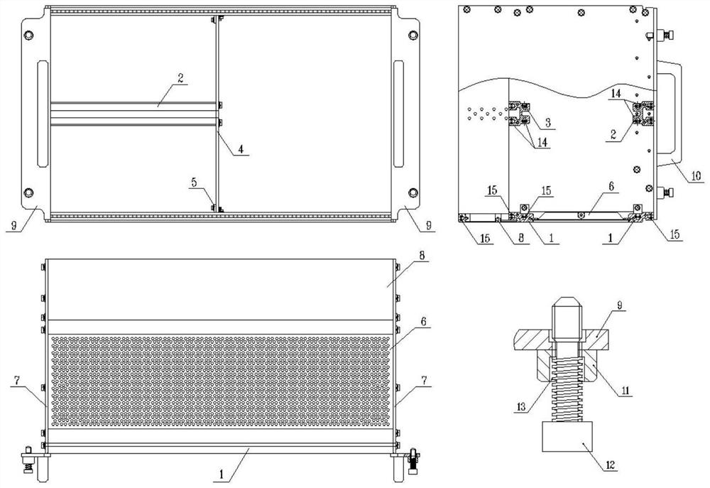
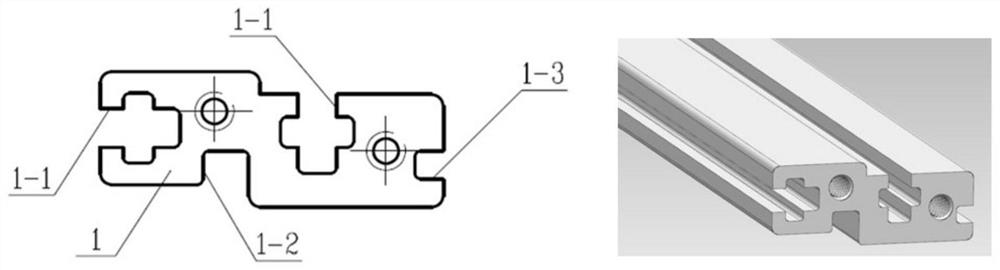
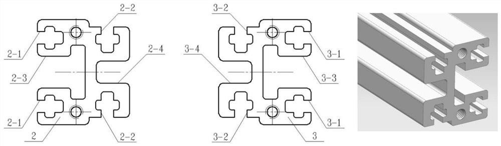
[0025] combine figure 1 , a plug-in box used in conjunction with a plug-in puller: mainly composed of 4 beams 1, 1 front middle beam 2, 1 rear middle beam 3, 1 partition plate 4, 4 corner pieces 5, 2 Cover plate 6, 2 side plates 7, 2 rear plates 8, 2 corner plates 9, 2 handles 10, 4 bushings 11, 4 screws 12, 4 springs 13, 8 short nut strips 14, 10 long nut strips 15 are assembled by connecting with fasteners. Beam 1 has a fixed rear plate 8 or a slide rail slot used in conjunction with a plug-in puller, and a slot that can be embedded in the cover plate; the cover pl...


PUM


Abstract

The invention proposes a plug-in box used in conjunction with a plug-in aid, including 4 beams, 2 cover plates, 2 side plates, and 2 rear plates, and each beam is provided with 2 bars for assembling nut strips Cross-shaped slot, 1 slide rail slot for use with the plug-in aid or to fix the rear plate, and 1 slot for fixing the cover plate; the front and rear upper beams and rear upper beams are respectively embedded in the front and rear sides of the upper cover In the slot of the beam, the front and rear sides of the lower cover plate are respectively embedded in the slot of the front lower beam and the rear lower beam; the upper and lower rear panels are L-shaped parts, which are inserted into the rear upper beam and the rear lower beam. The fixed connection between the two is realized in the slide rail groove, and together with the upper and lower cover plates, the complete top and bottom surfaces of the box are formed; the side plates are fixed with the left and right ends of the beam, cover plate and rear plate, together with the top and bottom surfaces It forms a complete subrack frame; the corner plates are set on both sides of the subrack frame for fixing with the cabinet. The plug-in box of the present invention is light in weight and small in height and size, and the plug-in box of the present invention does not need to be equipped with an auxiliary plug-in and pull-out device.

Description

technical field [0001] The invention relates to the structural technology of electronic equipment, in particular to a plug-in box used in conjunction with a plug-in auxiliary device. Background technique [0002] In the currently known plug-in box, when the plug-in is equipped with an electrical connector such as VPX with a large plug-in force, it is required that each plug-in must be equipped with a plug-in auxiliary device, and the plug-in plug is inserted into the plug-in plug with the lever force generated by the plug-in plug-in. When inserting and unplugging the plug-in, the plug-in assistant on the plug-in will transfer the force to the plug-in box. Because the plug-in force of the electrical connector is too large, the plug-in box will be deformed, and the force point of the contact between the plug-in box and the plug-in plug-in will be worn out. Special auxiliary plugs with longer lever arms and chassis with higher weight and strength are also required, and the cos...

Claims


Application Information

Patent Timeline
Patent Type & Authority Patents(China)
IPC IPC(8): H05K7/14H05K7/18
CPCH05K7/1409H05K7/1418H05K7/1425H05K7/183
Inventor 赵文生李龙冯静梁雪松张云泽陆幸骏董智鼎张方驹
Owner 扬州船用电子仪器研究所
Features
  • R&D
  • Intellectual Property
  • Life Sciences
  • Materials
  • Tech Scout
  • Unparalleled Data Quality
  • Higher Quality Content
  • 60% Fewer Hallucinations
Learn More