

Body cover device for car
A technology for body covers and automobiles, which is applied to vehicle parts, transportation and packaging, removable outer sheaths, etc., can solve the problems of trunk lid deformation, low rigidity of the trunk lid, falling off of mounting parts, etc., to restrain the load Effect
- Summary
- Abstract
- Description
- Claims
- Application Information
AI Technical Summary
Problems solved by technology
Method used
Image

Examples
no. 1 example
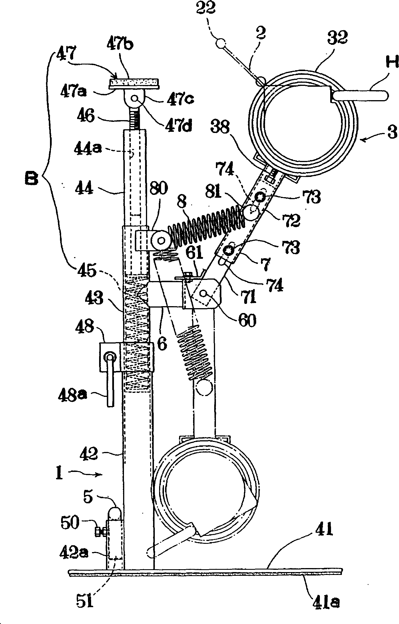
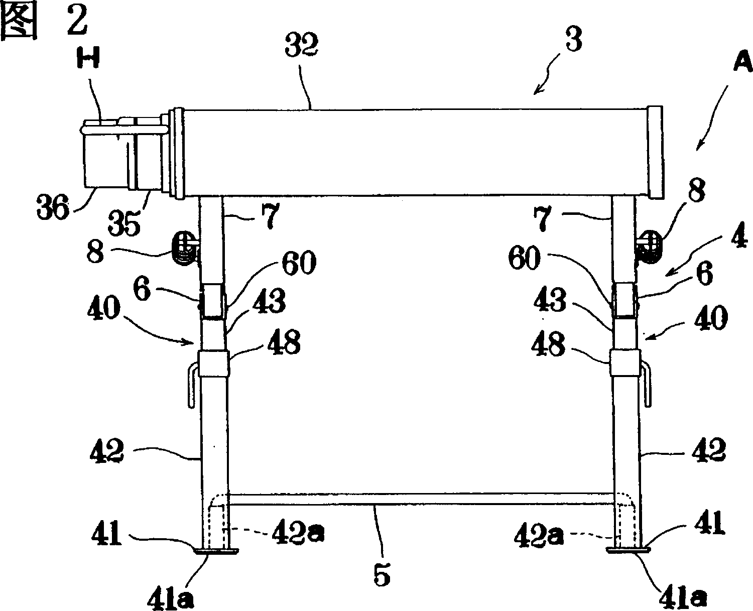
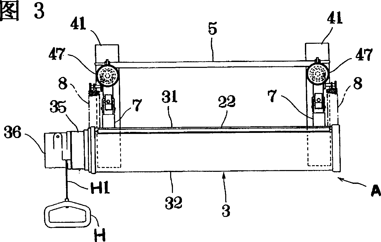
[0068] figure 1 It is a side view of the automobile body cover device (hereinafter referred to as [cover device]) A of the first embodiment, Fig. 2 is a front view of the same cover device A, Fig. 3 is a plan view of the same cover device, Figure 4 Shows the usage status of the device.
[0069] Such as Figure 4 As shown, the cover device A is configured to be accommodated in the trunk 10 of the automobile 1 for use, and the vehicle body cover 2 for the automobile can be pulled out semi-automatically and rolled up automatically. Figure 4 Among them, 11 is a trunk lid, 12 is a rear view glass, and 13 is a rear seat.
[0070] Such as figure 1 - As shown in Fig. 3, the cover device A is to erect the device body that can be drawn out and rolled up to form the vehicle body cover 2 on the column 4 in a swingable manner, and an elastic support member that can be freely stretched out is set on the column 4 B, the elastic support member B is accommodated in the trunk 10 in a stat...
no. 2 example
[0112] Below, refer to Figure 11-Figure 15 A second embodiment of the present invention will be described.
[0113] This is the case where the device main body 3 described in the first embodiment is detachably mounted on the column 4, and other configurations are basically the same as those of the first embodiment. Therefore, for the constituent elements in this embodiment, the same symbols as those in the first embodiment are used in the drawings for the same elements as those in the first embodiment.
[0114] Such as Figure 11 , Figure 13 and Figure 14 As shown, the loading and unloading structure of the present embodiment is that a short rail 75 is established on the front end of the body arm 7 of the column 4, and a sliding part 32A is formed on the outer casing 32 of the device body 3, and the sliding part 32A has a structure corresponding to the above-mentioned guide rail 75. Corresponding sliding plane.
[0115] One side edge of the guide rail 75 is bent inwardly...
no. 3 Embodiment
[0128] Below, refer to Figure 16-18 A third embodiment of the present invention will be described.
[0129] In this embodiment, first, the structure of the locking member described in the second embodiment is simplified while its function remains unchanged, making it more cost-effective.
[0130]That is to say, the lock member M' of this embodiment is a member that pivotally supports the front ends of the rotation lever constituting pieces M1', M1' standing from the base end of the ヘ-shaped operation piece M13' to the left and right. On the locking member mounting plate 76, and pivotally support the pivot pin MP1' on the approximately central position of the rotating rod constituting pieces M1', M1', a hook-shaped part made of spring steel and bent at the front end is formed. M21A, an overall arc-shaped locking plate spring M21' is installed on the pivot pin MP1'.
[0131] After the above-mentioned hook portion M21A hooks the locking edge 32A′ on the side of the device body...
PUM
 Abstract
Description
Claims
Application Information