Engine thrust plate crimping equipment

A technology of crimping equipment and thrust plates, which is applied in the direction of mechanical equipment, engine components, metal processing equipment, etc., can solve the problems of unguaranteed assembly quality, non-fitting of the rear end surface of the tile main bearing cap, uncontrollable operation process, etc.

Pending Publication Date: 2021-05-04
安徽创联汽车零部件有限公司
View PDF0 Cites 0 Cited by
  • Summary
  • Abstract
  • Description
  • Claims
  • Application Information

AI Technical Summary

Problems solved by technology

[0003] The traditional method is to manually press the tiles into place with ordinary installation tools. However, due to the difference in human strength, this operation process is uncontrollable, and the ...

Method used


Image

  • Engine thrust plate crimping equipment
  • Engine thrust plate crimping equipment
  • Engine thrust plate crimping equipment

Examples


Embodiment Construction

[0020] The present invention will be further described below in conjunction with specific embodiment and accompanying drawing, set forth more details in the following description so as to fully understand the present invention, but the present invention can be implemented in many other modes different from this description obviously, Those skilled in the art can make similar promotions and deductions based on actual application situations without violating the connotation of the present invention, so the content of this specific embodiment should not limit the protection scope of the present invention.

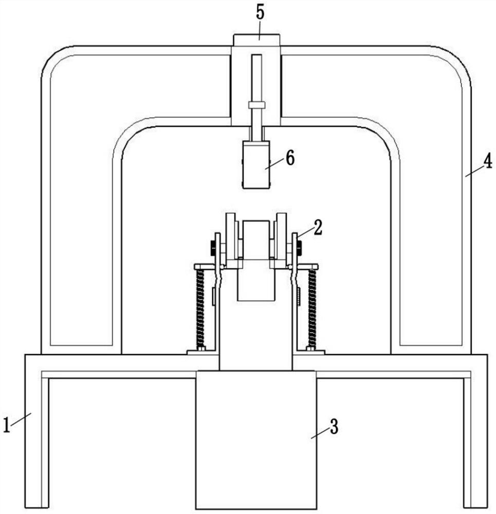
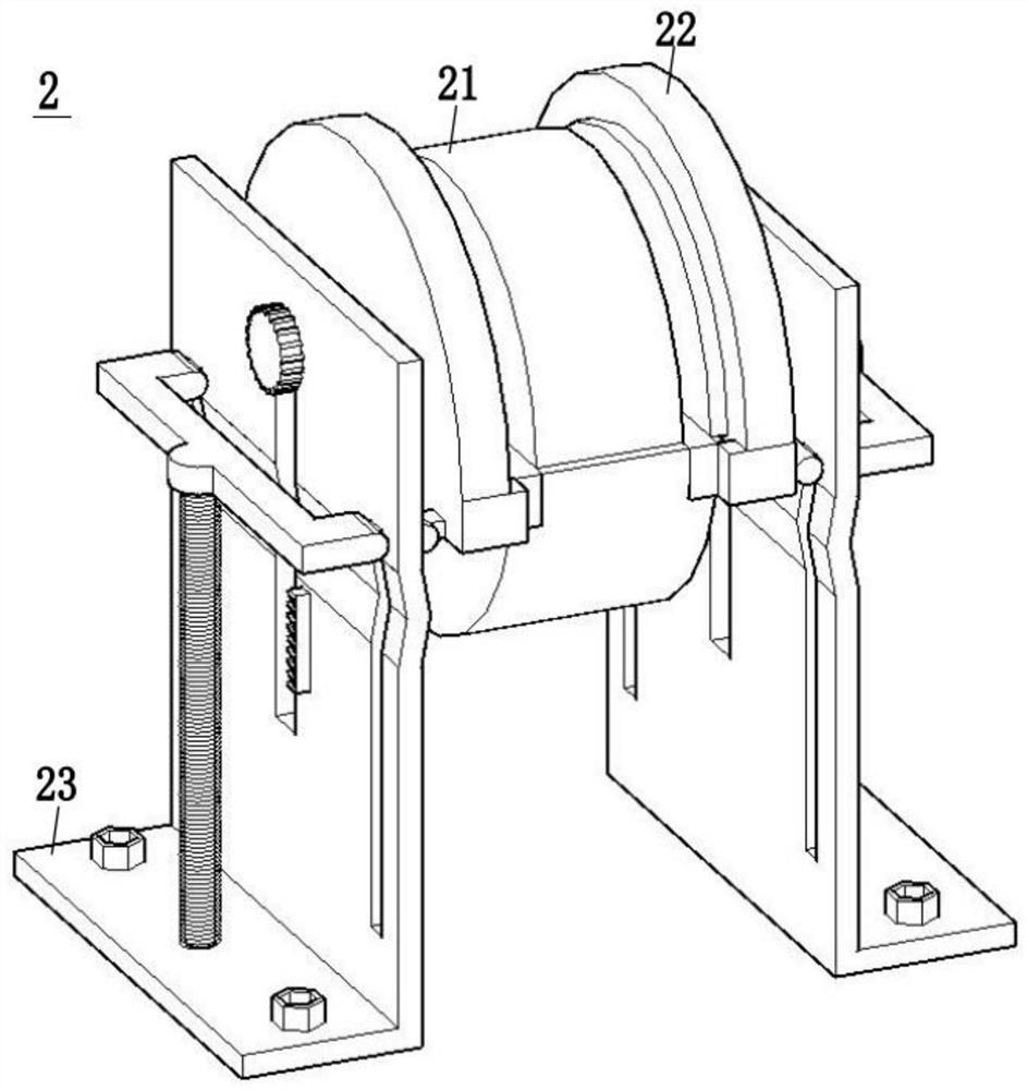
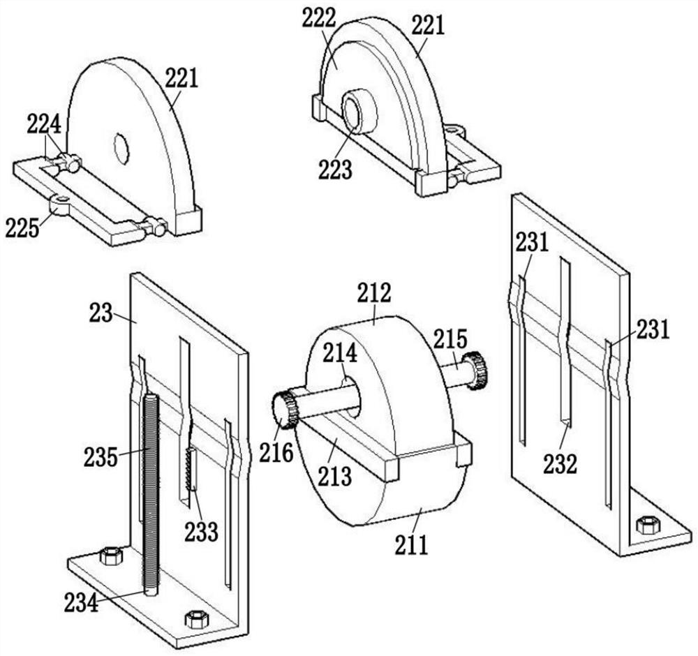
[0021] Such as figure 1 As shown, the engine thrust plate crimping equipment includes: workbench 1, riveting device 2, warehouse 3, mounting frame 4, oil cylinder 5, and pressing device 6;

[0022] A rectangular through opening is provided in the middle of the workbench 1, and a warehouse 3 is provided below the rectangular through opening of the workbench 1, a riveting device...


PUM


Abstract

The invention relates to the field of engine assembly, in particular to engine thrust plate crimping equipment. The engine thrust plate crimping equipment comprises a workbench, a riveting device, a warehouse, a mounting frame, an oil cylinder and a pressing device; the riveting device comprises a first assembling table, a second assembling table and two supporting plates; and the two supporting plates are fixed to the top face of the workbench and located on the two sides of a rectangular through opening of the supporting plates. According to the equipment, a tile and the thrust plate are riveted through downward pressing of the oil cylinder, and the riveting process is automatic, so that the situation that the quality of manual crimping cannot be guaranteed is prevented.

Description

technical field [0001] The invention relates to the field of engine assembly, in particular to an engine thrust plate crimping device. Background technique [0002] The thrust plate is a kind of sliding bearing of the engine. It mainly plays the role of axial support of the crankshaft in the engine. While ensuring the axial rotation of the crankshaft, it prevents the axial movement of the crankshaft. When installing the thrust plate into the engine, it needs to be Riveted with tiles. [0003] The traditional method is to manually press-fit the tiles in place with ordinary installation tools, but due to the difference in human strength, this operation process is uncontrollable, and the assembly quality cannot be guaranteed, resulting in a gap between the rear end face of the tile and the rear end of the main bearing cap. The end faces do not fit together, so the crankshaft axially moves in a small range, which affects the operation of the engine, and the efficiency of manual...

Claims


Application Information

Patent Timeline
IPC IPC(8): B21D39/00B21D43/20B21D43/02B21D53/84
CPCB21D39/00B21D43/20B21D43/02B21D53/84
Inventor 陈新法陈文进
Owner 安徽创联汽车零部件有限公司
Why Eureka
Try Eureka