Thrust shoe inlaying riveting machine

A thrust shoe and riveting machine technology, applied in metal processing equipment, feeding devices, positioning devices, etc., can solve problems such as affecting the operation of the engine, the rear surface of the main bearing cover of the tile does not fit, and the crankshaft is moving.

Inactive Publication Date: 2021-05-11
淮南冠东信息科技有限公司
View PDF0 Cites 0 Cited by
  • Summary
  • Abstract
  • Description
  • Claims
  • Application Information

AI Technical Summary

Problems solved by technology

[0003] The traditional method is to use ordinary installation tools to press the tiles in place. However, due to the difference in human strength, this operation process is uncon...

Method used


Image

  • Thrust shoe inlaying riveting machine
  • Thrust shoe inlaying riveting machine
  • Thrust shoe inlaying riveting machine

Examples


Embodiment Construction

[0021] The present invention will be further described below in conjunction with specific embodiment and accompanying drawing, set forth more details in the following description so as to fully understand the present invention, but the present invention can be implemented in many other modes different from this description obviously, Those skilled in the art can make similar promotions and deductions based on actual application situations without violating the connotation of the present invention, so the content of this specific embodiment should not limit the protection scope of the present invention.

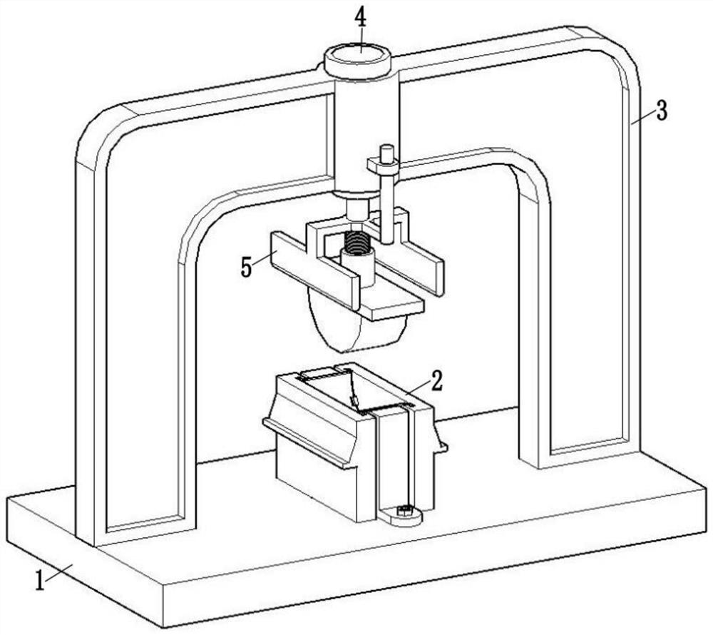
[0022] Such as figure 1 As shown, the thrust tile inlaid riveting machine includes: workbench 1, crimping device 2, mounting frame 3, oil cylinder 4, and pressing device 5;

[0023] The workbench 1 is used to support the crimping device 2 and the mounting frame 3, the mounting frame 3 is used to support the oil cylinder 4, and the pressing device 5 is connected to the oil cyli...


PUM


Abstract

The invention relates to the field of engine assembly, in particular to a thrust shoe inlaying riveting machine. The thrust shoe inlaying riveting machine comprises a workbench, a crimping device, a mounting frame, an oil cylinder and a downward pressing device, wherein the mounting frame is erected on the workbench, the oil cylinder is arranged on the mounting frame, and the lower end of a telescopic shaft of the oil cylinder is provided with the downward pressing device. According to the thrust shoe inlaying riveting machine, a shoe and a thrust plate are riveted through downward pressing of the oil cylinder, and the riveting process is automatic, so that the situation that the quality of manual crimping cannot be guaranteed is prevented.

Description

technical field [0001] The invention relates to the field of engine assembly, in particular to a thrust shoe inlaid riveting machine. Background technique [0002] The thrust plate is a kind of sliding bearing of the engine. It mainly plays the role of axial support of the crankshaft in the engine. While ensuring the axial rotation of the crankshaft, it prevents the axial movement of the crankshaft. When installing the thrust plate into the engine, it needs to be Riveted with tiles. [0003] The traditional method is to use ordinary installation tools to press the tiles in place. However, due to the difference in human strength, this operation process is uncontrollable, and the assembly quality cannot be guaranteed. The end faces do not fit together, so the crankshaft moves axially in a small range, which affects the operation of the engine. Contents of the invention [0004] Therefore, the present invention is made in view of the above-mentioned problems. The purpose of...

Claims


Application Information

Patent Timeline
IPC IPC(8): B21D39/02B21D43/00
CPCB21D39/02B21D43/003
Inventor 陈文山
Owner 淮南冠东信息科技有限公司
Why Eureka
Try Eureka