Earthquake source mechanism inversion method and device based on rock characteristics

A focal mechanism and rock technology, applied in the field of seismic focal mechanism inversion method and device based on rock characteristics, can solve the problems that the simulation results have multiple solutions, and the real and effective focal mechanism cannot be obtained

Active Publication Date: 2021-05-04
CHINA UNIV OF MINING & TECH (BEIJING)
View PDF9 Cites 6 Cited by
  • Summary
  • Abstract
  • Description
  • Claims
  • Application Information

AI Technical Summary

Problems solved by technology

[0003] The purpose of the present invention is to provide a method and device for seismic focal mechanism inversion based on rock characteristics, so as to alleviate the technical problems in the prior art that the simulation results have multiple solutions and cannot obtain a real and effective seismic focal mechanism

Method used


Image

  • Earthquake source mechanism inversion method and device based on rock characteristics
  • Earthquake source mechanism inversion method and device based on rock characteristics
  • Earthquake source mechanism inversion method and device based on rock characteristics

Examples


Embodiment 1

[0029] According to an embodiment of the present invention, an embodiment of a seismic source mechanism inversion method based on rock characteristics is provided. It should be noted that the steps shown in the flow chart of the accompanying drawings can be implemented in a computer system such as a set of computer-executable instructions and, although a logical order is shown in the flowcharts, in some cases the steps shown or described may be performed in an order different from that shown or described herein.

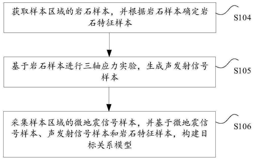
[0030] figure 1 A flow chart of a source mechanism inversion method based on rock characteristics provided by an embodiment of the present invention, such as figure 1 As shown, the method includes the following steps:

[0031] Step S101, collecting micro-seismic signals in the target monitoring area. In this embodiment, the definition of the above-mentioned target monitoring area can be determined according to the actual situation. For example, the target monitorin...

Embodiment 2

[0058] An embodiment of the present invention provides a rock feature-based focal mechanism inversion device, the rock feature-based focal mechanism inversion device is mainly used to implement the rock feature-based focal mechanism inversion method provided in the above content of Embodiment 1, The following is a specific introduction to the source mechanism inversion device based on rock characteristics provided by the embodiment of the present invention.

[0059] Figure 4 It is a schematic structural diagram of a source mechanism inversion device based on rock characteristics provided by an embodiment of the present invention. Such as Figure 4 As shown, the source mechanism inversion device based on rock characteristics mainly includes: acquisition unit 11, prediction unit 12 and inversion unit 13, wherein:

[0060] Acquisition unit 11, for collecting the microseismic signal of target monitoring area;

[0061] The prediction unit 12 is used to predict the target rock c...


PUM


Abstract

The invention provides an earthquake source mechanism inversion method and device based on rock characteristics, and relates to the technical field of micro-earthquake monitoring. The method comprises the steps: firstly collecting a micro-earthquake signal of a target monitoring region; predicting target rock features corresponding to the micro-earthquake signal based on the target relation model; and finally, based on the target rock characteristics, inverting an earthquake source mechanism of a fracture event in the target monitoring region. According to the invention, the authenticity of the data used for inverting the earthquake source mechanism can be ensured by collecting the micro-earthquake signal of the target monitoring region, and the rock characteristics of the fracture event in the target monitoring region can be obtained by predicting the target rock characteristics corresponding to the micro-earthquake signal according to the target relation model. The rock characteristics can avoid multiplicity of solutions of the earthquake source mechanism, and then a real, effective and unique earthquake source mechanism is obtained.

Description

technical field [0001] The invention relates to the technical field of microseismic monitoring, in particular to a rock feature-based focal mechanism inversion method and device. Background technique [0002] In the process of microseismic monitoring, whether it is to monitor hydraulic fracturing or to ensure the stability of carbon dioxide migration and storage during the injection process, the rupture signals of underground reservoirs and other media due to the destruction of the original stress balance will be collected. , and then invert the focal mechanism. However, the existing focal mechanism inversion methods are only simulated in experiments, and the simulation results have multiple solutions. Therefore, the existing technology faces the technical problem that the focal mechanism has multiple solutions and cannot further obtain a true and effective focal mechanism. Contents of the invention [0003] The purpose of the present invention is to provide a method and ...

Claims


Application Information

Patent Timeline
Patent Type & Authority Applications(China)
IPC IPC(8): G01V1/28G01V1/30
CPCG01V1/288G01V1/306G01V2210/62
Inventor 郑晶孟令彬彭苏萍
Owner CHINA UNIV OF MINING & TECH (BEIJING)
Why Eureka
Try Eureka