Trigger type clutch mechanism and filling equipment
A clutch mechanism, triggering technology, applied in the field of mechanical equipment, can solve the problems of inability to reset the piston rod, affecting the use effect, perfusion accuracy error, etc.
- Summary
- Abstract
- Description
- Claims
- Application Information
AI Technical Summary
Problems solved by technology
Method used
Image
Examples
Embodiment 1
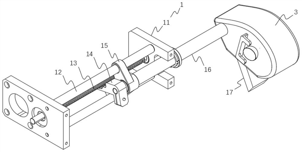
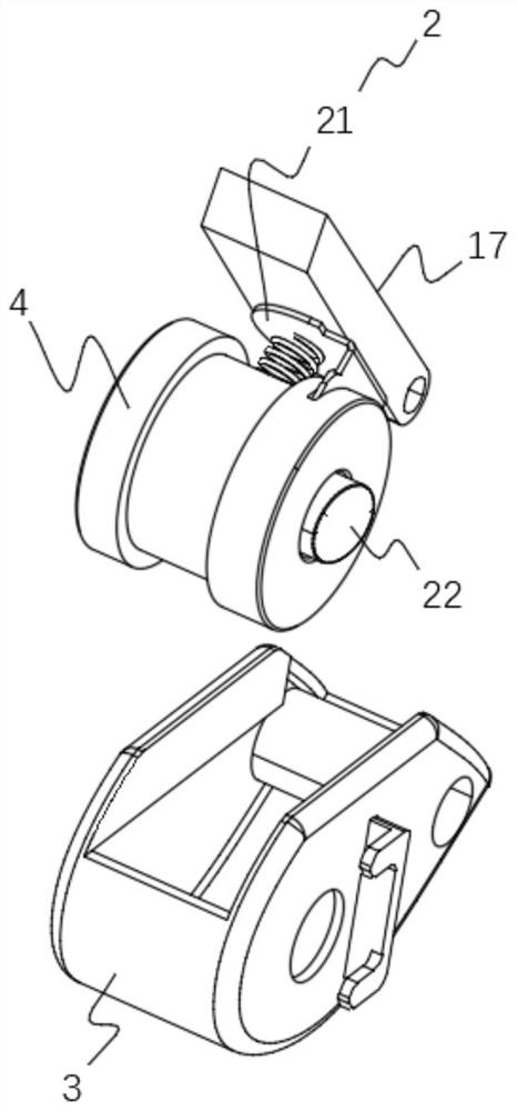
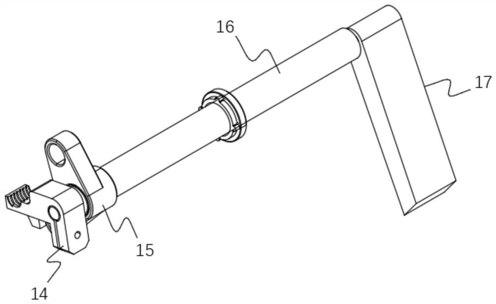
[0063] figure 1 It is a schematic diagram of the overall structure of the clutch mechanism in Embodiment 1 of the present invention, figure 2 It is a schematic structural diagram of the trigger assembly and the holding member in Embodiment 1 of the present invention, image 3 It is a schematic structural diagram of the push assembly in Embodiment 1 of the present invention, such as Figure 1-3 As shown, a trigger clutch mechanism in this embodiment includes: a transmission assembly 1 , a trigger assembly 2 , a holding member 3 and a fixing seat 4 .
[0064] The transmission assembly 1 includes: a limit plate 11, a first guide rod 12, a screw rod 13, a clutch jaw 14, a bearing slider 15, a push assembly 16 and a resisting plate 17, the first guide rod 12 and the screw rod 13 are parallel to each other is set on the limit plate 11, the proximal end of the push assembly 16 passes through the limit plate 11 and is fixedly connected with the clutch jaw 14 and the bearing slider ...
Embodiment 2
[0083] Figure 8 It is a schematic diagram of the overall structure in Embodiment 2 of the present invention. Embodiment 2 of the present invention provides a filling device for manipulating a container to complete the filling action. The container includes: a cylinder and a piston rod, and the filling device includes: a shell Body 5, driving mechanism 6 and the clutch mechanism, the driving mechanism 6 is set in the housing 5, and the cylinder is fixedly connected to the housing 5, one end of the piston rod is connected to the grip 3, and on the grip 3 When the piston rod is installed on the top, the trigger clutch mechanism is engaged with the drive mechanism 6, and when the piston rod is not installed on the holding member 3, the trigger clutch mechanism is separated from the drive mechanism 6, and the drive mechanism 6 is used when the transmission part group 1 is engaged with the clutch mechanism , drive the grip 3 to move, and make the piston rod on the grip 3 move relat...
PUM
 Abstract
Description
Claims
Application Information
 - R&D
- Intellectual Property
- Life Sciences
- Materials
- Tech Scout
- Unparalleled Data Quality
- Higher Quality Content
- 60% Fewer Hallucinations
Browse by: Latest US Patents, China's latest patents, Technical Efficacy Thesaurus, Application Domain, Technology Topic, Popular Technical Reports.
© 2025 PatSnap. All rights reserved.Legal|Privacy policy|Modern Slavery Act Transparency Statement|Sitemap|About US| Contact US: help@patsnap.com


