
Aero-engine jet pipe and expansion piece pull rod structure thereof

A technology of aero-engine and tie-rod structure, which is applied in the direction of machines/engines, jet propulsion devices, etc., and can solve problems such as large thrust loss, unstable airflow, and vibration of expansion plates

Active Publication Date: 2021-05-07
AECC SHENYANG ENGINE RES INST
View PDF15 Cites 4 Cited by
  • Summary
  • Abstract
  • Description
  • Claims
  • Application Information

AI Technical Summary

Problems solved by technology

[0003] During the working process of the aero-engine, in order to obtain better thrust performance, it is necessary to adjust the nozzle throat area and nozzle outlet area according to the actual working conditions. Currently, a convergent plate adjustment mechanism is designed to drive each convergent plate to wind and connect with the nozzle. The connection part at the outlet end of the cylinder rotates to realize the adjustment of the throat area of ​​the nozzle, and a plurality of tie rods are designed to connect each expansion piece and the fixed end, and each expansion piece rotates under the drive of the corresponding convergence piece, thereby changing the nozzle outlet area. Since the length of each tie rod is fixed, when the nozzle throat area is constant, the nozzle outlet area is also determined, that is, there is a one-to-one correspondence between the nozzle outlet area and the nozzle throat area. Excellent thrust performance, in addition, in the state of small drop pressure ratio, the airflow flowing through the nozzle is in an over-expansion state, which causes a large loss of thrust and unstable airflow, which easily causes the vibration of the expansion plate

Method used


Image

  • Aero-engine jet pipe and expansion piece pull rod structure thereof
  • Aero-engine jet pipe and expansion piece pull rod structure thereof
  • Aero-engine jet pipe and expansion piece pull rod structure thereof

Examples


Embodiment Construction

[0032] In order to make the technical solution of the present application and its advantages clearer, the technical solution of the present application will be further clearly and completely described in detail below in conjunction with the accompanying drawings. It can be understood that the specific embodiments described here are only part of the application Examples are only used to explain the present application, not to limit the present application. It should be noted that, for the convenience of description, only the parts related to the present application are shown in the drawings, and other relevant parts can refer to the general design. In the case of no conflict, the embodiments in the application and the technologies in the embodiments Features can be combined with each other to obtain new embodiments.

[0033] In addition, unless otherwise defined, the technical terms or scientific terms used in the description of the application shall have the usual meanings und...


PUM


Abstract

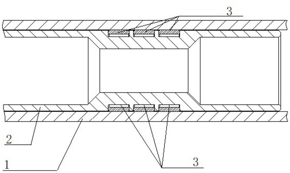
The invention belongs to the technical field of aero-engine jet pipe structure design, and particularly relates to an expansion piece pull rod structure of an aero-engine jet pipe. The expansion piece pull rod structure comprises: a first connecting rod, wherein a connecting hole is formed in one end of the first connecting rod; a second connecting rod, wherein one end of the second connecting rod is inserted into the connecting hole and can axially move relative to the first connecting rod, and an annular clamping groove is formed between the second connecting rod and the connecting hole; and an elastic ring, wherein the elastic ring is clamped in the annular clamping groove and can generate friction force between the second connecting rod and the first connecting rod so as to prevent the second connecting rod from moving relative to the first connecting rod in the axial direction. In addition, the invention relates to the aero-engine jet pipe structure comprising the expansion piece pull rod structure of the aero-engine jet pipe.

Description

technical field [0001] The application belongs to the technical field of aero-engine nozzle structure design, and in particular relates to an aero-engine nozzle and its expansion segment tie rod structure. Background technique [0002] The nozzle is an important part of the aero-engine, which is used to expel the high-temperature and high-pressure gas after the turbine to expand and accelerate, thereby generating engine thrust. , one end of each converging piece is hinged at the outlet end of the nozzle connecting cylinder, distributed along the circumferential direction, and the adjacent converging pieces are in sealing contact to form the nozzle converging section, and the radial dimension of the nozzle converging section is away from the nozzle The direction of the connecting cylinder shrinks gradually to form the throat of the nozzle; one end of each expansion piece is correspondingly hinged on the other end of a convergent piece, and the adjacent expansion pieces are in...

Claims


Application Information

Patent Timeline
IPC IPC(8): F02K1/15F02K1/78F02K1/82
CPCF02K1/15F02K1/78F02K1/82
Inventor 王殿磊周东旭宁怀松
Owner AECC SHENYANG ENGINE RES INST
Learn More