
Medical tool for department of stomatology

A medical tool and stomatological technology, applied in the field of stomatological medical tools, can solve the problems of inconvenient operation, inconvenient matching installation and detection, etc., and achieve the effect of convenient position conversion

Inactive Publication Date: 2021-05-11
郭柔汐
View PDF1 Cites 0 Cited by
  • Summary
  • Abstract
  • Description
  • Claims
  • Application Information

AI Technical Summary

Problems solved by technology

[0004] There is a phenomenon that it is not convenient to carry out matching installation and detection, which will cause some inconvenience in operation and needs to be improved

Method used


Image

  • Medical tool for department of stomatology
  • Medical tool for department of stomatology
  • Medical tool for department of stomatology

Examples


Embodiment 1

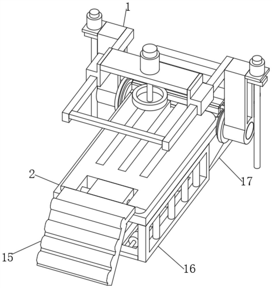
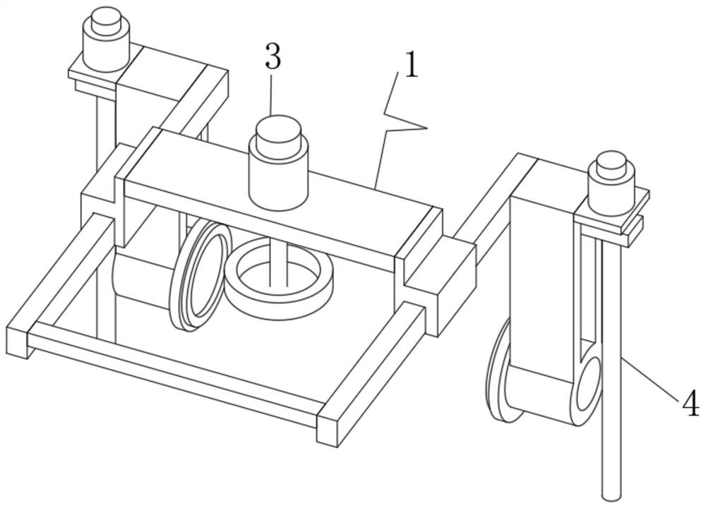
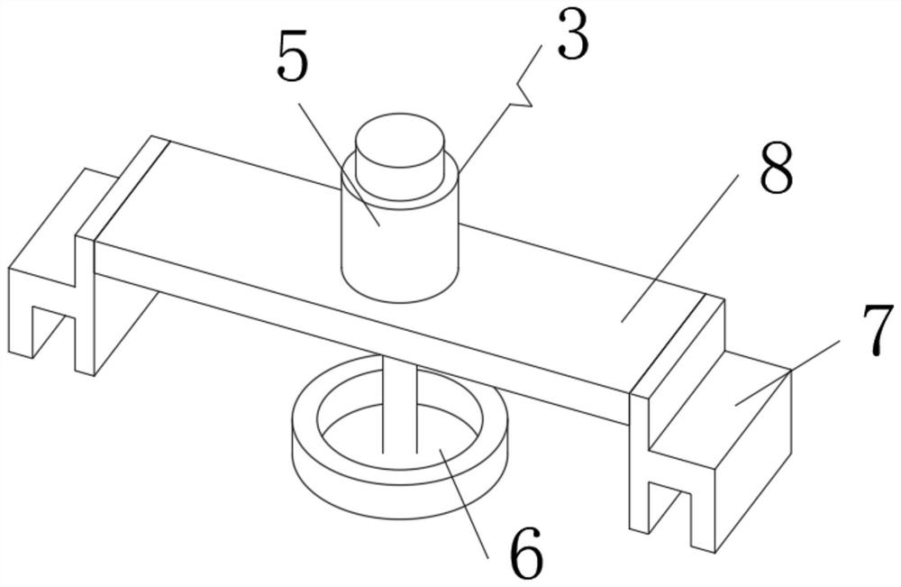
[0038] A dental medical tool, such as Figure 1-9 As shown, it includes a top device 1, the bottom of the top device 1 is fixedly connected with a bottom device 2, the top device 1 includes a movable structure 3 and a restriction structure 4, the movable structure 3 is arranged at the center of the inner end of the top device 1, and the restriction structure 4 is fixedly connected At the side end position of the movable structure 3, the movable structure 3 includes a hydraulic press 5, an installation chuck 6, a matching frame 7 and a cross frame 8, the hydraulic press 5 is installed on the top of the inner end of the movable structure 3, and the lower end of the hydraulic press 5 and the installation chuck The 6-phase telescopic connection, the hydraulic press 5 and the installation chuck 6 are connected with the horizontal frame 8 in position, the side end position of the horizontal frame 8 is fixedly connected with the matching frame 7, and the limiting structure 4 includes ...

Embodiment 2

[0042] On the basis of Example 1, such as Figure 10 As shown, the foot plate 15 also includes an inflatable bag 28 , and the inflatable bag 28 is arranged at the central inner end of the cushion pad 20 .

[0043] When this embodiment is in use, by installing the inflatable bag 28 at the inner end of the foot plate 15, the inflatable bag 28 is located at the inner end of the cushion pad 20, and the filling work of gas can be carried out through the outside world, so as to realize the inflation of the cushion pad 20 and help the cushion pad 20. The adjustment of the comfort level can be performed through the air bag 28 to discharge the gas at the inner end, which facilitates the adjustment and replacement work and improves the overall performance.

[0044] Working principle: When work is required, the user installs the top device 1. The inner end of the top device 1 is composed of a movable structure 3 and a restrictive structure 4. The movable structure 3 can slide on the rest...


PUM


Abstract

The invention discloses a medical tool for the department of stomatology. The medical tool comprises a top device; the lower portion of the top device is fixedly connected with a bottom device; the top device comprises a movable structure and a limiting structure; the movable structure is arranged in the center of the inner end of the top device; the limiting structure is fixedly connected to the side end of the movable structure; the movable structure comprises a hydraulic machine, a mounting chuck, a matching frame and a transverse frame; the hydraulic machine is mounted at the top of the inner end of the movable structure; the lower end of the hydraulic machine is telescopically connected with the mounting chuck; the hydraulic machine and the mounting chuck are in limiting connection with the transverse frame; the side end of the transverse frame is fixedly connected with the matching frame; the limiting structure comprises a rotating shaft frame, a lead screw, a sleeve frame, a motor and a transverse block plate; and the rotating shaft frame is arranged at the bottom of the inner end of the limiting structure. The invention provides the medical tool for the department of stomatology, and the purpose of inner end connection is achieved through the arrangement of the top device.

Description

technical field [0001] The invention relates to the technical field of stomatology equipment, in particular to a medical tool for stomatology. Background technique [0002] According to Chinese Patent No. CN106562867A, the present invention relates to medical equipment, in particular to a chair for oral surgery. In the existing oral surgery, the patient must sit on a chair, and then use the oral mirror to go deep into the patient's mouth, and then perform the operation. The chair and the oral mirror are separated, which is inconvenient to use, and the height of the existing chair is fixed and cannot be adjusted arbitrarily. Provided is a chair for oral surgery, in which a dental mirror is fixed on the seat, and the height of the chair can be adjusted arbitrarily, the structure is simple, and the use is convenient. [0003] Dental medical tools can help to carry out the work of dental inspection tools. Through the setting of dental medical tools, the overall inspection treat...

Claims


Application Information

Patent Timeline
Patent Type & Authority Applications(China)
IPC IPC(8): A61G15/00A61G15/10A61G15/12A61G15/14
CPCA61G15/00A61G15/10A61G15/12A61G15/14A61G2203/70A61G2210/00
Inventor 不公告发明人
Owner 郭柔汐
Learn More