
Internal waterproof microswitch

A technology of micro switch and inner cavity, which is applied in the direction of electric switches, contacts, electrical components, etc.

Pending Publication Date: 2021-05-11
广东丰实卫奇电子科技有限公司
View PDF0 Cites 0 Cited by
  • Summary
  • Abstract
  • Description
  • Claims
  • Application Information

AI Technical Summary

Problems solved by technology

At present, the above two types of switches in the market cannot meet the existing market demand

Method used


Image

  • Internal waterproof microswitch
  • Internal waterproof microswitch
  • Internal waterproof microswitch

Examples


Embodiment 1

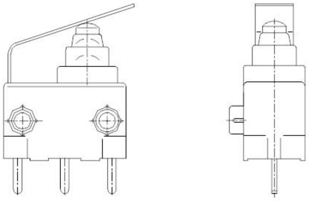
[0030] see Figure 1-9 , in an embodiment of the present invention, an internal waterproof micro switch, including a button 2, an upper cover 3, a shrapnel 5, a terminal 7, an upper terminal 9, a base 10, a solid rubber sleeve 11 and a UL wire 12, and the top of the base 10 is provided with Inner cavity 101, the terminal 7 is overmolded in the inner cavity 101 of the base, and the upper surface of the terminal 7 is flat with the bottom surface of the inner cavity 101, and the center of the terminal 7 is provided with a front clip 701 and a rear clip 702, and the terminals contact The position is provided with a first contact hole 703, and a terminal contact 8 is riveted in the contact hole 703. An intermediate terminal is also arranged on the terminal 7. The intermediate terminal is provided with an insertion hole 704, a terminal tip 705 and an insertion clip 706. The terminal 9 is provided with a pin 91 and a third contact hole 92, and the pin 91 is movably inserted into the ...

Embodiment 2

[0040] As another implementation of the product, this embodiment is further improved on the basis of Embodiment 1. The improvement is that: one end of the UL wire 12 is riveted with a plug-in terminal 14, and the plug-in terminal 14 is installed in the socket 13, the combination of the UL wire 12, the plug terminal 14 and the socket 13 can be directly inserted into the frame of the solid rubber sleeve 11, and the plug terminal is closely combined with the terminal tip 705 to realize communication. The other end of the UL wire 12 is connected with a waterproof socket 15, and a waterproof plug 16 is plugged in the waterproof socket 15, so that the whole electric part can be completely waterproofed.

[0041] It will be apparent to those skilled in the art that the present invention is not limited to the details of the exemplary embodiments described above, but that the invention can be embodied in other specific forms without departing from the spirit or essential characteristics ...

Embodiment 3

[0043] see Figure 10 , this embodiment is further improved on the basis of Embodiment 1, the improvement is that: the middle terminal is bent upwards into a "Z" shape, and a fourth contact hole 714 is provided. The shrapnel contact 6 moves up and down, contacts the third contact hole 703 and the fourth contact hole 714 up and down, and switches in both directions.


PUM


Abstract

The invention discloses an internal waterproof microswitch, and the microswitch comprises an elastic piece, a terminal, an upper terminal and a base; an inner cavity is formed in the top of the base, the terminal is plastic-coated in the inner cavity of the base, the upper surface of the terminal is flush with the bottom surface of the inner cavity, a front clamping piece and a rear clamping piece are arranged in the center of the terminal, a first contact hole is formed in the contact position of the terminal, a terminal contact is riveted in the contact hole, the terminal is also provided with a middle terminal, the middle terminal is provided with a plugging hole, a terminal tip part and a plugging clip, the upper terminal is provided with a pin and a third contact hole, and the pin is movably embedded into the plugging hole; a front bayonet, a rear bayonet, a second contact hole and an elastic tongue piece are arranged on the elastic piece, and the front bayonet and the rear bayonet correspond to the front clamping piece and the rear clamping piece. The service life is up to more than one million times, small spacing conduction is achieved, the working stroke is up to more than 1 mm, the size is small, installation and use are convenient, the minimum installation height ranges from 3.5 mm to 7.5 mm, and the operating force of a product can be increased to more than 5N through a double-generation operating force device.

Description

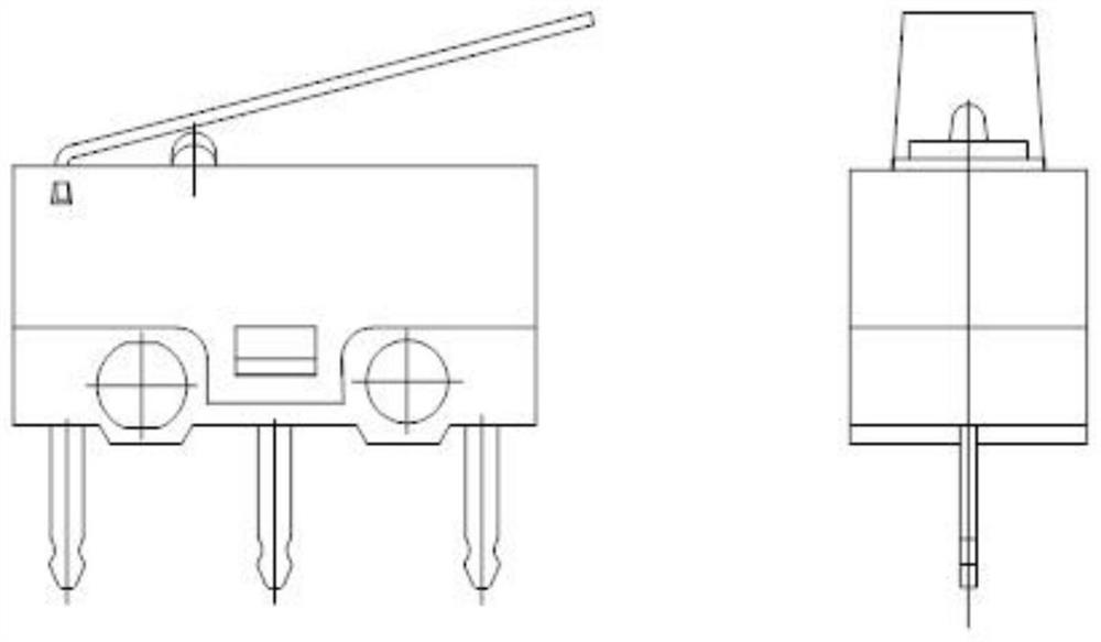
technical field [0001] The invention relates to a waterproof micro switch, in particular to an inner waterproof micro switch. Background technique [0002] A switch is an electronic component that can open a circuit, pass it through, interrupt the current, or allow the current to flow to other circuits. The waterproof micro switch switch is widely used in printers, electronic door locks, smart meters, water meters, car door locks and other fields, and has the characteristics of high frequency of use and strong randomness of operation. [0003] However, the switches currently on the market are not waterproof, or are waterproof but have a large volume, and there is no installation positioning hole or only one installation positioning hole, such as ( Figure II ) One kind includes, button, upper cover, base, terminal, shrapnel. The button drives the shrapnel, and the shrapnel switches up and down between the terminals, so as to realize the on-off function. The switch terminal ...

Claims


Application Information

Patent Timeline
Patent Type & Authority Applications(China)
IPC IPC(8): H01H13/10H01H13/52H01H13/06H01H13/02H01H1/58
CPCH01H1/5866H01H13/02H01H13/06H01H13/10H01H13/52
Inventor 黄炎陈列
Owner 广东丰实卫奇电子科技有限公司
Learn More