Crank, pedal mechanism and wheelchair

A technology of cranks and pedals, which is applied in the fields of pedal mechanisms, wheelchairs, and cranks, and can solve the problem of limited posture of the user's movement.

Active Publication Date: 2021-05-14
北京理工华汇智能科技有限公司
View PDF8 Cites 0 Cited by
  • Summary
  • Abstract
  • Description
  • Claims
  • Application Information

AI Technical Summary

Problems solved by technology

The structure of the existing crank can only realize the movement of the feet with the pedal mechanism, which leads to the limited movement posture of the user

Method used


Image

  • Crank, pedal mechanism and wheelchair
  • Crank, pedal mechanism and wheelchair
  • Crank, pedal mechanism and wheelchair

Examples


Embodiment Construction

[0034] In order to make the object, technical solution and advantages of the present invention clearer, the present invention will be further described in detail below in combination with specific embodiments and with reference to the accompanying drawings. It should be understood that these descriptions are exemplary only, and are not intended to limit the scope of the present invention. Also, in the following description, descriptions of well-known structures and techniques are omitted to avoid unnecessarily obscuring the concept of the present invention.

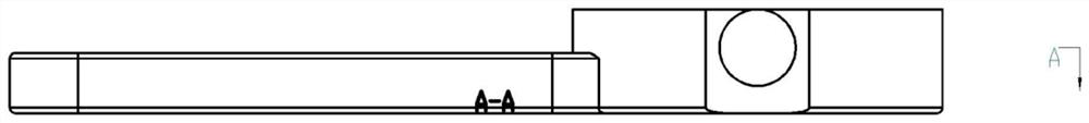
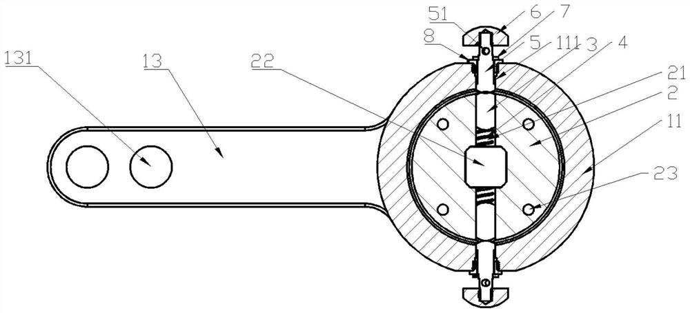
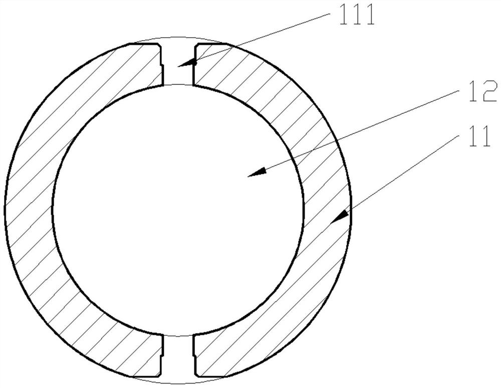
[0035] figure 1 is a side view of a crank according to an embodiment of the invention; figure 2 is a sectional view of a crank according to an embodiment of the present invention; image 3 is a cross-sectional view of an assembly part according to an embodiment of the present invention; Figure 4 is a top view of an assembly part according to an embodiment of the present invention; Figure 5 is a cross-sectional view...


PUM


Abstract

The invention discloses a crank, a pedal mechanism and a wheelchair. The crank comprises a crank body (1), a matching piece (2), a first limiting component (3) and an elastic component (4). When the through hole of an assembling part and the hole of the matching part are located at the opposite positions, under the elastic force of the elastic component, one end of the first limiting component can be located in the hole, the other end of the first limiting part is located in the through hole, then the rotating motion between the assembling part and the matching part is limited, and then the crank can controllably rotate. When the two ends of the crank are connected with a pedal and the output shaft of a driving assembly respectively, the pedal can rotate by 0 degree or 180 degrees through rotation of the crank.

Description

technical field [0001] The invention relates to the technical field of machinery, in particular to a crank, a pedal mechanism and a wheelchair. Background technique [0002] At present, one end of the existing crank is generally connected to the pedal, and the other end is connected to the output shaft of the drive assembly in the pedal structure. The structure of the existing crank can only realize the movement of the feet apart by the pedal mechanism, resulting in limited movement posture of the user. Contents of the invention [0003] (1) Purpose of the invention [0004] The purpose of the present invention is to provide a kind of crank, pedal mechanism and wheelchair, and this crank is provided with the elastic component first stopper, is provided with fitting part and is sleeved in the fitting part in the fitting hole of fitting part, can make fitting hole and fit Parts achieve relative rotational movement. When the through hole of the fitting part is in the oppos...

Claims


Application Information

Patent Timeline
IPC IPC(8): A61G5/00A61G5/10A61G5/12A61H1/02
CPCA61G5/00A61G5/1051A61G5/128A61H1/0237A61H2201/0149A61H2201/1207A61H2205/10A61G2203/10
Inventor 张伟民卢浩胡学海池志鹏黄强
Owner 北京理工华汇智能科技有限公司
Why Eureka
Try Eureka