Camera device

A technology for cameras and equipment, applied in the field of camera equipment, can solve problems such as camera equipment hitting, and achieve the effect of avoiding harmful distortions

Active Publication Date: 2021-06-11
AXIS
View PDF9 Cites 0 Cited by
  • Summary
  • Abstract
  • Description
  • Claims
  • Application Information

AI Technical Summary

Problems solved by technology

[0006] In other scenarios, camera equipment may be hit with a hammer or other hard object with malicious intent

Method used


Image

  • Camera device
  • Camera device
  • Camera device

Examples


Embodiment Construction

[0046] The present invention will now be described more fully hereinafter with reference to the accompanying drawings, in which presently preferred embodiments of the invention are shown. However, the invention may be embodied in many different forms and should not be construed as limited to the embodiments set forth herein; rather, these embodiments are provided for thoroughness and completeness, and will fully convey the scope of the invention to those skilled in the art. .

[0047] The camera device 100 will be described below with reference to the drawings.

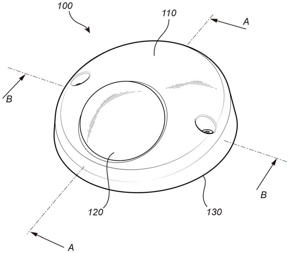
[0048] figure 1 An embodiment of the camera device 100 is illustrated. The disclosed embodiment includes a base member 130, a housing 110 and surrounding camera unit 200 (eg figure 2 Shown) the dome window 120.

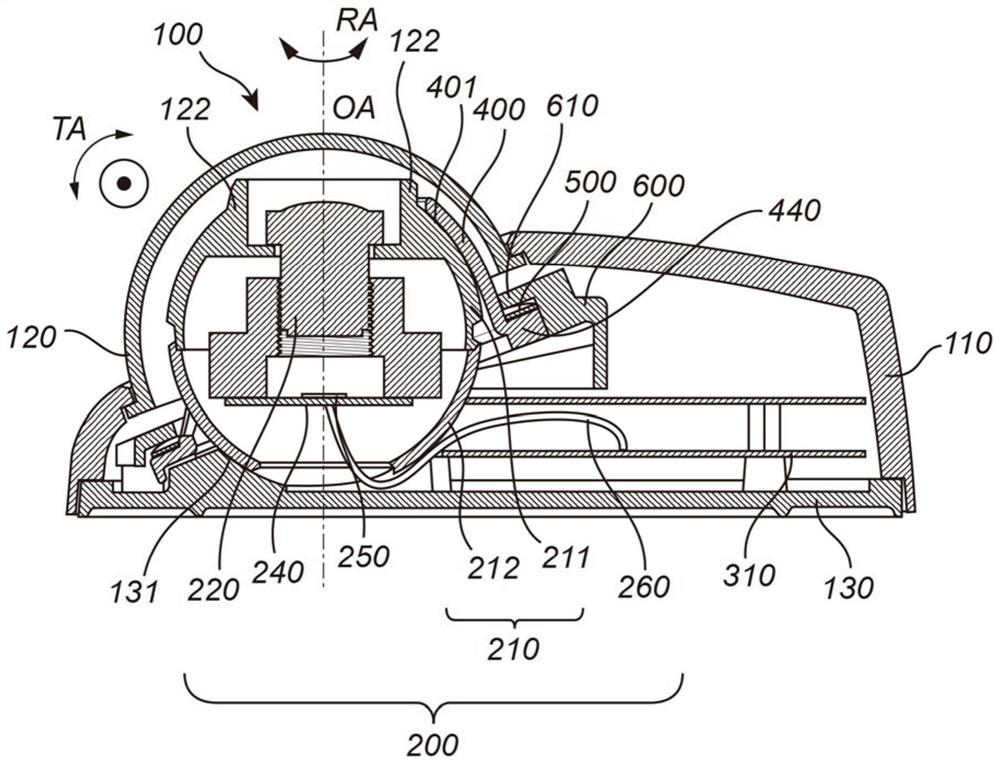
[0049] figure 2 public figure 1 A cross-sectional view of the camera device 100 disclosed in . The housing 110 accommodates the base member 130 , the camera unit 200 and the cover 400 . The housing 11...


PUM


Abstract

The invention relates to a camera device comprising a camera unit comprising an outer shell having a spherical shape and being provided with an equatorial groove having a start and an end, a base member provided with a seating, and a cover provided with a pivot defining a tilting axis and an aperture for providing a free line of sight for the camera unit. The camera unit is arranged between the seating and the cover such that the pivot is received by the equatorial groove and such that the cover and the seating of the base member are pressed against the outer shell of the camera unit from opposing sides thereof. The pivot is arranged on a lug adjoining the cover via a lug transition and defined by a slit such that the lug is laterally displaceable in a direction parallel with the tilting axis in response to the pivot being subjected to a force having a component in said direction.

Description

technical field [0001] The present invention relates to a camera device. Background technique [0002] Camera equipment such as network cameras can be used in many different situations both indoors and outdoors. Such camera equipment may be a surveillance or surveillance camera. [0003] The camera device should also be able to withstand a certain level of shock, such as an object suddenly touching the camera device. [0004] In outdoor environments, camera equipment should be able to withstand different weather conditions, such as rain or wind. [0005] Some camera devices may be subject to vibrations, for example if the camera device is placed on a vehicle. In this case, it is desirable for the camera equipment to withstand vibration and maintain a set orientation so that the intended field of view is maintained. [0006] In other scenarios, the camera equipment may be hit with a hammer or other hard object with malicious intent. Some camera devices are made with hard...

Claims


Application Information

Patent Timeline
Patent Type & Authority Applications(China)
IPC IPC(8): H04N5/225F16M13/02
CPCF16M13/02H04N23/50H04N23/51H04N23/55H04N23/54G08B13/19619G08B13/1963G03B17/02G03B17/561H04N7/18H04N23/58H04N23/695
Inventor 守矢怜子
Owner AXIS
Why Eureka
Try Eureka