Glass aspherical lens manufacturing equipment for precise mold pressing

A technology for manufacturing equipment and aspheric surfaces, applied in glass manufacturing equipment, manufacturing tools, glass molding, etc., can solve problems such as high manufacturing costs, glass lens errors, waste of resources, etc., to reduce manual operations, stabilize processing and manufacturing, reduce effect of error

Active Publication Date: 2022-02-18
江西超联光电科技有限公司
View PDF7 Cites 0 Cited by
  • Summary
  • Abstract
  • Description
  • Claims
  • Application Information

AI Technical Summary

Problems solved by technology

[0005] Therefore, the purpose of the present invention is to overcome that the existing manufacturing equipment generally places the glass lens on the workbench without directly clamping the glass lens, resulting in The molded glass lens has certain errors, waste of resources, and high manufacturing cost. To provide a precision molded glass aspheric lens that can clamp the glass lens, reduce errors, save resources, and reduce manufacturing costs. equipment

Method used


Image

  • Glass aspherical lens manufacturing equipment for precise mold pressing
  • Glass aspherical lens manufacturing equipment for precise mold pressing
  • Glass aspherical lens manufacturing equipment for precise mold pressing

Examples


Embodiment 1

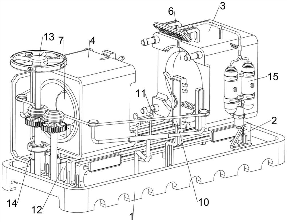
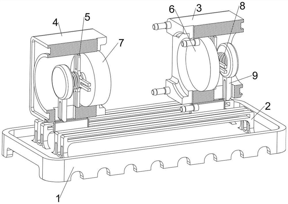
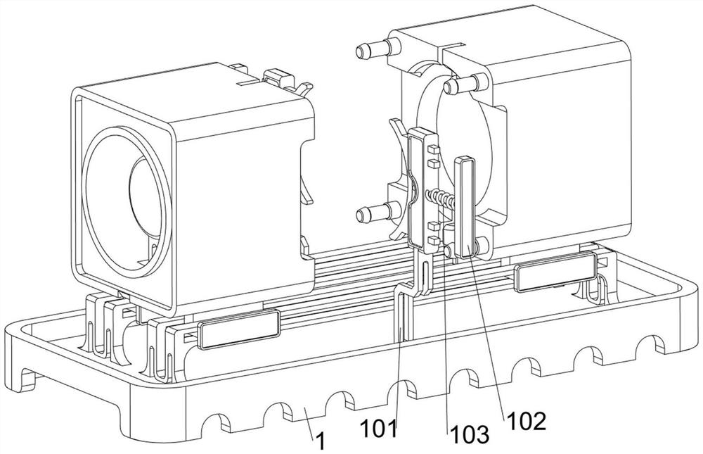
[0090] A precision molded glass aspheric lens manufacturing equipment such as Figure 1-Figure 6 As shown, it includes a bottom plate 1, a first support frame 2, a first sliding module 3, a second sliding module 4, a first fixed block 5, a first sliding mold 6, a second sliding mold 7, a first return spring 8, The first connecting block 9, the clamping mechanism 10 and the placement mechanism 11, the first supporting frame 2 is provided on the front and rear sides of the top of the bottom plate 1, and the first sliding module 3 is slidable between the right sides of the two first supporting frames 2 , the second sliding module 4 is slidingly arranged between the left sides of the two first support frames 2, and the first fixing block 5 is arranged inside the first sliding module 3 and the second sliding module 4, and the first fixing block on the right side 5. The left sliding type is provided with a first sliding mold 6. The first sliding mold 6 is slidingly matched with the ...

Embodiment 2

[0097] On the basis of Example 1, such as figure 1 , Figure 7 , Figure 8 , Figure 9 , Figure 10 , Figure 11 , Figure 12, Figure 13 , Figure 14 and Figure 15 As shown, the transmission mechanism 12 is also included, and the transmission mechanism 12 includes a support plate 121, a second connection block 122, a rack 123, a second wedge block 124, a first connection spring 125, a motor 126 and a first gear 127, and the bottom plate 1 There are support plates 121 on the left and right sides of the top, and a second connecting block 122 is provided on the left and right sides of the top of the bottom plate 1, and a rack is provided between the supporting plate 121 on the same side and the upper part of the second connecting block 122 in a sliding manner 123, two racks 123 outer tops are slidingly provided with a second wedge block 124, the second wedge block 124 on the left side is in contact with the second sliding module 4, and the second wedge block 124 on the ...


PUM


Abstract

The invention relates to manufacturing equipment, in particular to glass aspheric lens manufacturing equipment for precise mold pressing. The glass aspheric lens manufacturing equipment for precise mold pressing, which can clamp a glass lens, reduces errors, saves resources and reduces the manufacturing cost is provided. The equipment comprises first supporting frames arranged on the front side and the rear side of the top of a bottom plate correspondingly; a first sliding module arranged between the right sides of the two first supporting frames in a sliding mode; and a second sliding module arranged between the left sides of the two first supporting frames in a sliding mode. People firstly place the glass lens between two sliding clamps, then force is not applied to sliding clamps, and under the reset action of second reset springs, the sliding clamps move inwards to clamp the glass lens, so that the glass lens can be processed and manufactured more stably, and errors are reduced.

Description

technical field [0001] The invention relates to a manufacturing equipment, in particular to a precision molded glass aspherical lens manufacturing equipment. Background technique [0002] An aspheric lens refers to a lens whose surface is not spherical or cylindrical. In photography, a lens containing an aspheric optical element has a different surface curvature from an ordinary spherical lens. In order to pursue the thinness of the lens, it is necessary to change the surface of the lens. The current aspherical design corrects the image and solves the problem of distortion of the field of view. At the same time, it makes the lens lighter, thinner, and flatter, and still maintains excellent impact resistance, making it safe for the wearer to use. [0003] Traditional lenses are processed by grinding, which makes it difficult to produce high-precision aspheric lenses. Therefore, glass molding is currently the most suitable technology for producing aspheric optical lenses. Usin...

Claims


Application Information

Patent Timeline
Patent Type & Authority Applications(China)
IPC IPC(8): C03B23/031
CPCC03B23/031Y02P40/57
Inventor 董国强蔡福军
Owner 江西超联光电科技有限公司
Why Eureka
Try Eureka