U-shaped inclined tube for inclined tube thickener and splicing method of U-shaped inclined tube

A concentrator and inclined tube technology, applied in the direction of the settling tank, etc., can solve the problems of restricting sedimentation efficiency, complicated operation, overlapping of inclined tube sheets, etc.

Active Publication Date: 2021-05-14
ZHENGZHOU UNIV
View PDF4 Cites 0 Cited by
  • Summary
  • Abstract
  • Description
  • Claims
  • Application Information

AI Technical Summary

Problems solved by technology

[0005] In view of the above analysis, the present invention aims to provide a U-shaped inclined tube and its splicing method for the inclined tube thickener, so as to solve the phenomenon that the existing inclined tubes wil

Method used


Image

  • U-shaped inclined tube for inclined tube thickener and splicing method of U-shaped inclined tube
  • U-shaped inclined tube for inclined tube thickener and splicing method of U-shaped inclined tube
  • U-shaped inclined tube for inclined tube thickener and splicing method of U-shaped inclined tube

Examples


Embodiment 1

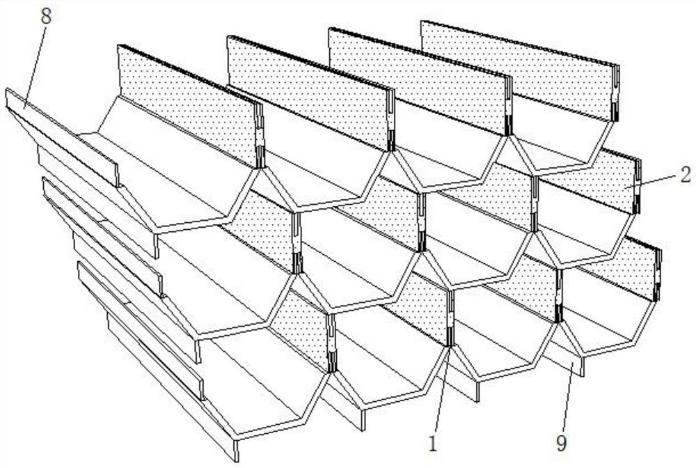
[0035] A specific embodiment of the present invention discloses a U-shaped inclined tube for an inclined tube thickener, including a corrugated sheet 1 and a parallel sheet 2; wherein there are multiple corrugated sheets 1 and parallel sheets 2, and the corrugated sheets 1 are arranged side by side cloth, and adjacent corrugated sheets 1 are connected by a plurality of parallel sheets 2, such as figure 1 shown.

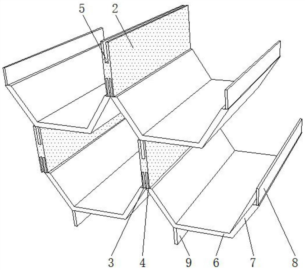
[0036] In a specific embodiment of the present invention, the upper and lower sides of the corrugated sheet 1 are provided with protruding plugs, the parallel sheet 2 is a plate-shaped structure, and the top and bottom of the parallel sheet 2 are provided with slots, and the slots at both ends of the parallel sheet 2 Cooperate with the plugs of the two corrugated sheets 1 respectively to realize the splicing combination of the corrugated sheet 1 and the parallel sheet 2. The U-shaped inclined tube of the present invention adopts the splicing method of snapping togeth...

Embodiment 2

[0054] A specific implementation of the present invention provides a method for splicing U-shaped inclined tubes used in inclined tube thickeners, comprising the following steps:

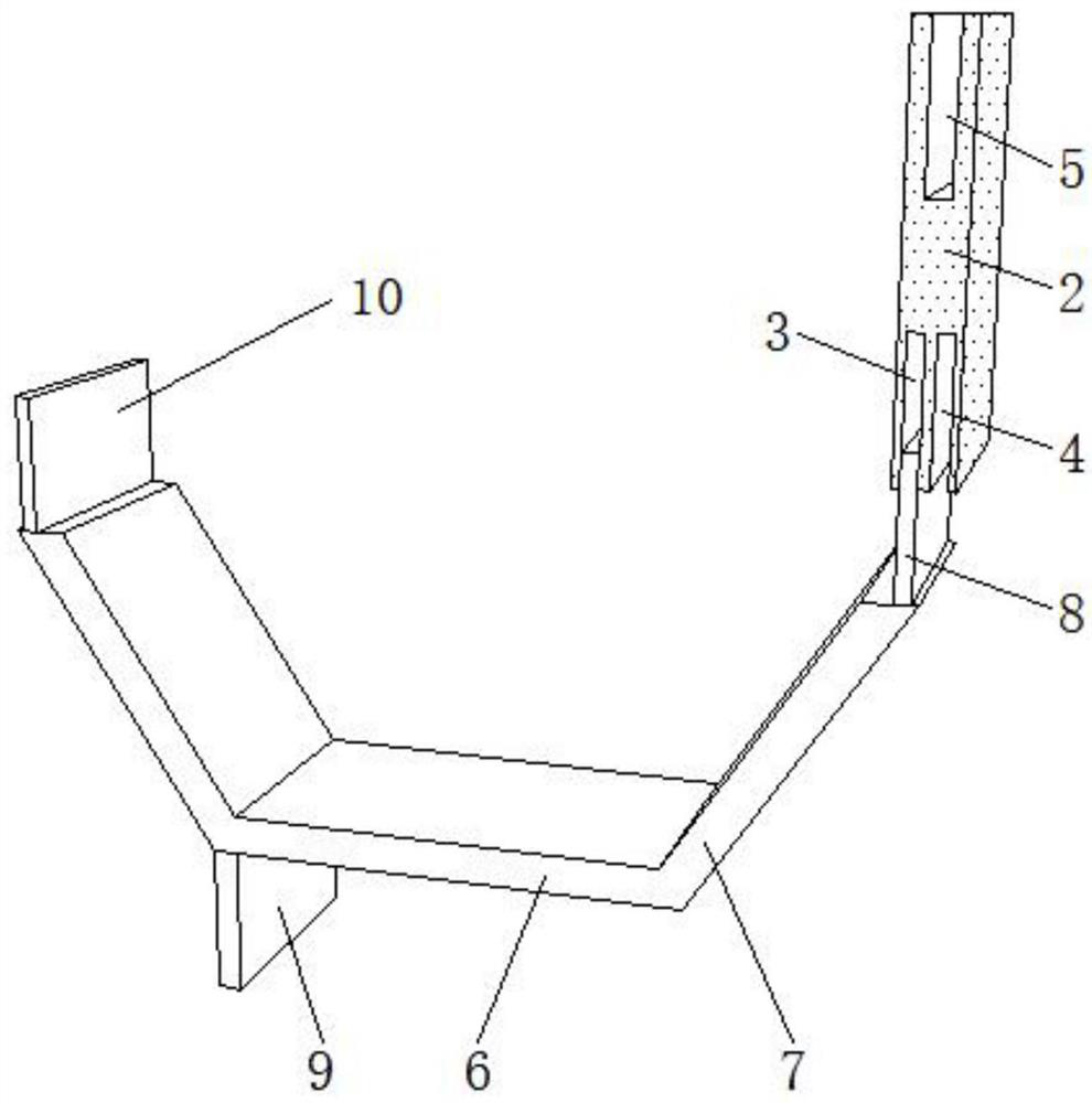
[0055] Step S1: Insert the first plug 8 on the surface of the first U-shaped piece 6 into the first concave groove 3 inside the parallel piece 2, and then insert the third plug 10 on the surface of the second U-shaped piece 6 into the parallel In the second concave groove 4 inside the sheet 2, such as image 3 shown.

[0056] Step S2: Repeat step S1 to obtain a continuous corrugated sheet 1 after splicing; a plurality of U-shaped sheets 6 are combined into a corrugated sheet 1 through parallel sheets 2 .

[0057] Step S3: Insert the second plug 9 of the new U-shaped sheet 6 into the third groove 5 of the parallel sheet 2 to obtain the next layer of corrugated sheet; through the insertion between the second plug 9 and the third groove 5 , to realize the connection between the multi-layer corrugated...


PUM


Abstract

The invention relates to a U-shaped inclined tube for an inclined tube thickener and a splicing method of the U-shaped inclined tube, belongs to the technical field of underground coal preparation, and solves the problems that the precipitation efficiency is low and the combination mode is complicated due to sheet overlapping during installation of the existing inclined tube. The U-shaped inclined tube comprises a plurality of layers of waveform sheets and a plurality of parallel sheets. Each layer of waveform sheet comprises a plurality of U-shaped sheets, and a first plug and a third plug are arranged at the two ends of each U-shaped sheet respectively. One end of each parallel sheet is provided with a first groove and a second groove, and the first plugs and the third plugs of the adjacent U-shaped sheets are respectively clamped to and connected with the first groove and the second groove of the same parallel piece to form a waveform sheet. A second plug is arranged at the bottom of each U-shaped sheet. A third groove is formed in the other end of each parallel sheet. The second plugs are connected with the third grooves in a clamped mode, and connection between the multiple layers of waveform sheets is achieved. Rapid splicing of the U-shaped inclined tube is achieved through mutual clamping of the waveform sheets and the parallel sheets.

Description

technical field [0001] The invention relates to the technical field of underground coal preparation, in particular to a U-shaped inclined pipe used in an inclined pipe thickener and a splicing method thereof. Background technique [0002] The inclined tube thickener is one of the most core equipment in the coal preparation process. It is widely used in coal preparation plants because of its high sedimentation efficiency and small footprint. There is almost no change in the type and process performance, and the honeycomb hexagonal inclined tube is basically used, but this inclined tube still has certain defects. [0003] The existing inclined tubes are simple to manufacture, but overlapping sheets will occur during installation, occupying the sedimentation area and restricting the sedimentation efficiency. At the same time, the existing inclined tubes are installed by ironing to form a huge and complete inclined tube block, the operation is very complicated. [0004] The in...

Claims


Application Information

Patent Timeline
IPC IPC(8): B01D21/02
CPCB01D21/02
Inventor 贾凯曹亦俊桂夏辉李国胜王志刚
Owner ZHENGZHOU UNIV
Why Eureka
Try Eureka