
Communication pole for multi-degree-of-freedom directional 5G antenna

A technology with degrees of freedom and communication poles, applied in the field of 5G antennas, can solve problems such as damage to communication poles, entanglement of vines and weeds, and rise in surface temperature

Pending Publication Date: 2021-05-14
管伟娴
View PDF0 Cites 1 Cited by
  • Summary
  • Abstract
  • Description
  • Claims
  • Application Information

AI Technical Summary

Problems solved by technology

[0003] Since the 5G antenna will generate a lot of heat during operation, the surface temperature of the multi-degree-of-freedom directional 5G antenna communication pole close to the 5G antenna will also be affected and rise. The strong wind blows and wraps around the surface of the communication pole. If it is not treated in time, it is easy to burn the vine-like hay on the surface of the communication pole, which will cause unnecessary damage to the communication pole.

Method used


Image

  • Communication pole for multi-degree-of-freedom directional 5G antenna
  • Communication pole for multi-degree-of-freedom directional 5G antenna
  • Communication pole for multi-degree-of-freedom directional 5G antenna

Examples


Embodiment 1

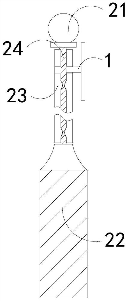
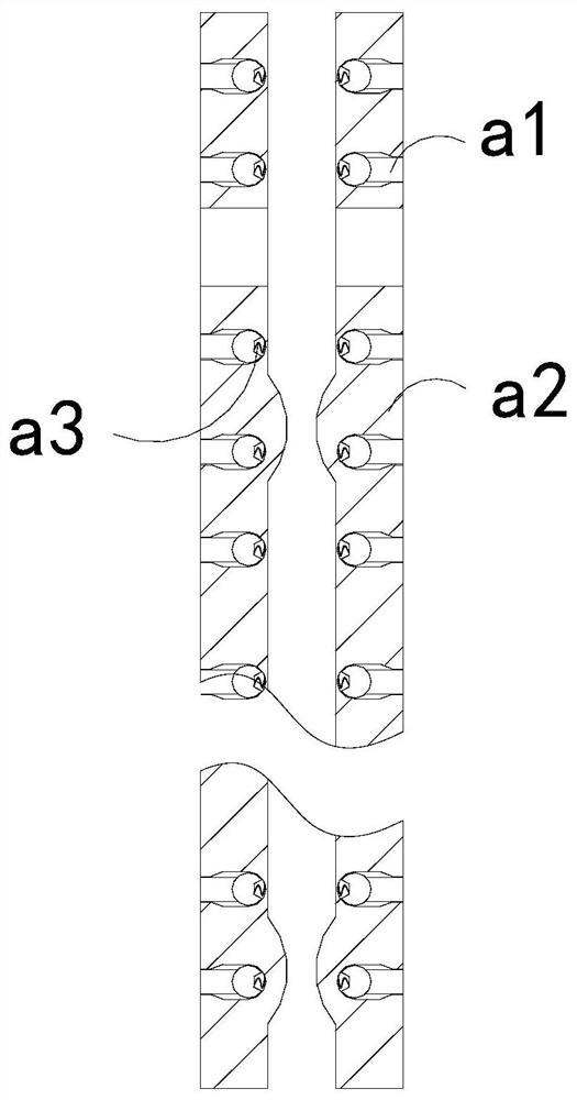
[0026] For example figure 1 -example Figure 5 Shown:

[0027] The present invention provides a multi-degree-of-freedom directional 5G antenna communication rod, the structure of which includes an adapter plate 1, a support rod 2, and a base 3. The adapter plate 1 is embedded in the upper end of the support rod 2, and the support rod 2 and The upper surface of the base 3 is welded; the support rod 2 includes an upper connecting block 21, a bottoming block 22, an outer rotating frame 23, and a central shaft 24, and the upper connecting block 21 is welded to the top position of the central shaft 24, and the The outer rotating frame 23 is movably engaged with the side of the central shaft 24 , and the central shaft 24 is embedded and fixed at the top position of the bottoming block 22 .

[0028] Wherein, the outer swivel frame 23 includes an overhanging block a1, a plate body a2, and a pullback bar a3, and the overhanging block a1 runs through the inner position of the pullback...

Embodiment 2

[0034] For example Figure 6 -example Figure 8 Shown:

[0035] Wherein, the crushing groove b2 includes a pullback bar b21, a bottoming plate b22, and an inwardly extending surface b23. The inwardly extending surface b23 is connected to the bottoming plate b22 through the pullback bar b21, and the vibration generated by the swinging reset of the mechanism can make the The inner extension surface b23 is repeatedly expanded and contracted under the cooperation of the pull-back bar b21, so that the inner extension surface b23 can eject the vine-like hay debris inside it.

[0036] Wherein, the inner extension surface b23 includes a connecting block c1, a ventilating cavity c2, a linkage rod c3, a plate c4, and a bumping block c5. c4 is an integrated structure, the linkage rod c3 is hinged to the outer side of the connection block c1, the impact block c5 is fixed at the front end of the linkage rod c3, and the impact block c5 is made of lead metal with relatively high density. ...


PUM


Abstract

The invention discloses a communication pole for a multi-degree-of-freedom directional 5G antenna. The communication rod structurally comprises a connecting plate, a supporting rod and a base, the connecting plate is embedded into the inner position of the upper end of the supporting rod, and the supporting rod is welded to the upper surface of the base. Through thrust generated by reverse air flow when an outward extending block extends outwards to outward swinging plates, the outer swing plates can swing towards the two sides along a combination block, then pull-back strips pull the outward extending blocks, crushing grooves can pull apart vine withered grass wound around the outer surfaces of the supporting rod under the cooperation of an outer contact plate, the two outer swing plates are closed and reset to extremely collide with each other to generate vibration, and an inner extending face can extend outwards under the cooperation of the pull-back strips, so that vine type withered grass chippings in a crushing groove can be ejected outwards, and the situation that the vine type withered grass chippings enter the crushing groove and are brought into a plate body together with the outer extending block, and consequently the vine type withered grass chippings are prone to being heated and burnt is effectively avoided.

Description

technical field [0001] The invention relates to the field of 5G antennas, in particular to a communication pole for multi-degree-of-freedom directional 5G antennas. Background technique [0002] The multi-degree-of-freedom directional 5G antenna communication pole is mainly used to fix and support the 5G antenna. By installing the 5G antenna on the connecting plate, the multi-degree-of-freedom directional 5G antenna communication pole can be used to fix the 5G antenna. , based on the above description, the inventors found that the existing multi-degree-of-freedom directional 5G antenna communication pole mainly has the following deficiencies, for example: [0003] Since the 5G antenna will generate a lot of heat during operation, the surface temperature of the multi-degree-of-freedom directional 5G antenna communication pole close to the 5G antenna will also be affected and rise. The strong wind blows and wraps around the surface of the communication pole. If it is not trea...

Claims


Application Information

Patent Timeline
Patent Type & Authority Applications(China)
IPC IPC(8): H01Q1/12
CPCH01Q1/12
Inventor 管伟娴
Owner 管伟娴
Learn More