Meat air-drying device
An air-drying device and meat technology, applied in the direction of hanging meat/sausage, processed meat, slaughtering, etc., can solve the problem of inconvenient control of the drying distance of meat
- Summary
- Abstract
- Description
- Claims
- Application Information
AI Technical Summary
Problems solved by technology
Method used
Image
Examples
Embodiment 1
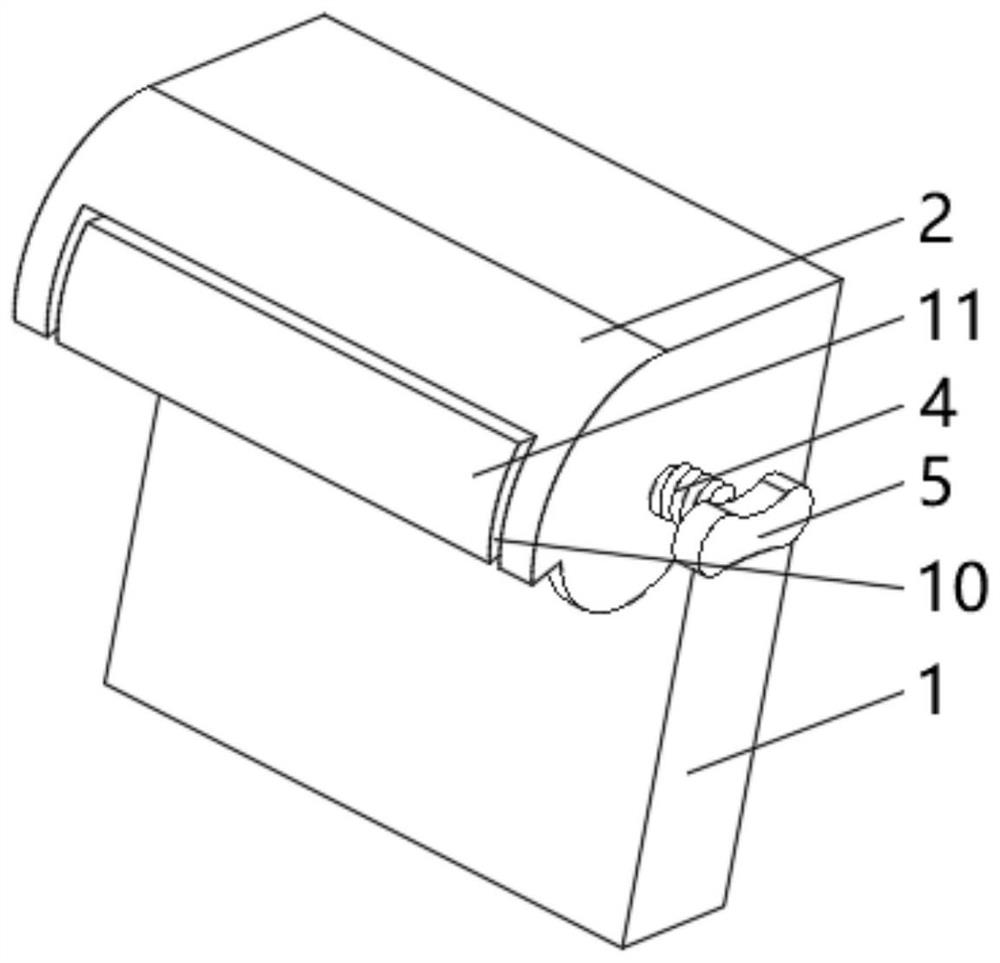
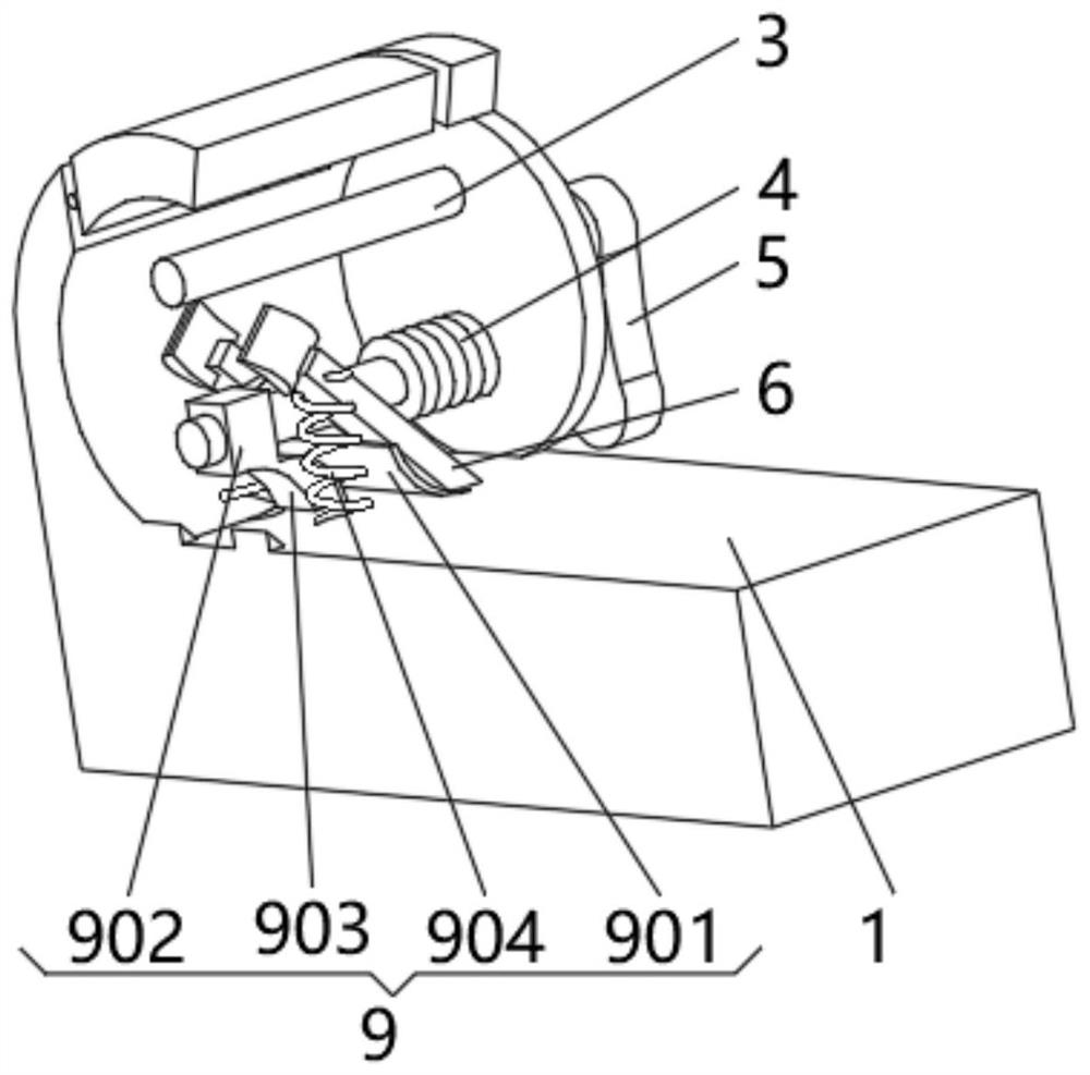
[0032] see Figure 1-3 , the present invention provides a technical solution: a meat air-drying device, comprising a support vertical plate 1, one side of the support vertical plate 1 is fixedly connected with a shielding frame 2, the bottom of the shielding frame 2 is designed as an opening, and the inner wall of the shielding frame 2 One side is respectively equipped with a sliding rod 3 and a rotating rod 4, and one end of the rotating rod 4 extending to the outside of the shielding frame 2 is fixedly connected with a rotating handle 5, and the end of the rotating rod 4 close to the rotating handle 5 is provided with an external thread, and the rotating rod 4 is connected to the shielding frame 2. The frame 2 is screwed, and the side of the support vertical plate 1 is symmetrically installed with a swing rod 6 close to the position of the rotation rod 4. The end of the swing rod 6 away from the support vertical plate 1 is fixedly connected with a lifting plate 7, and the out...
Embodiment 2
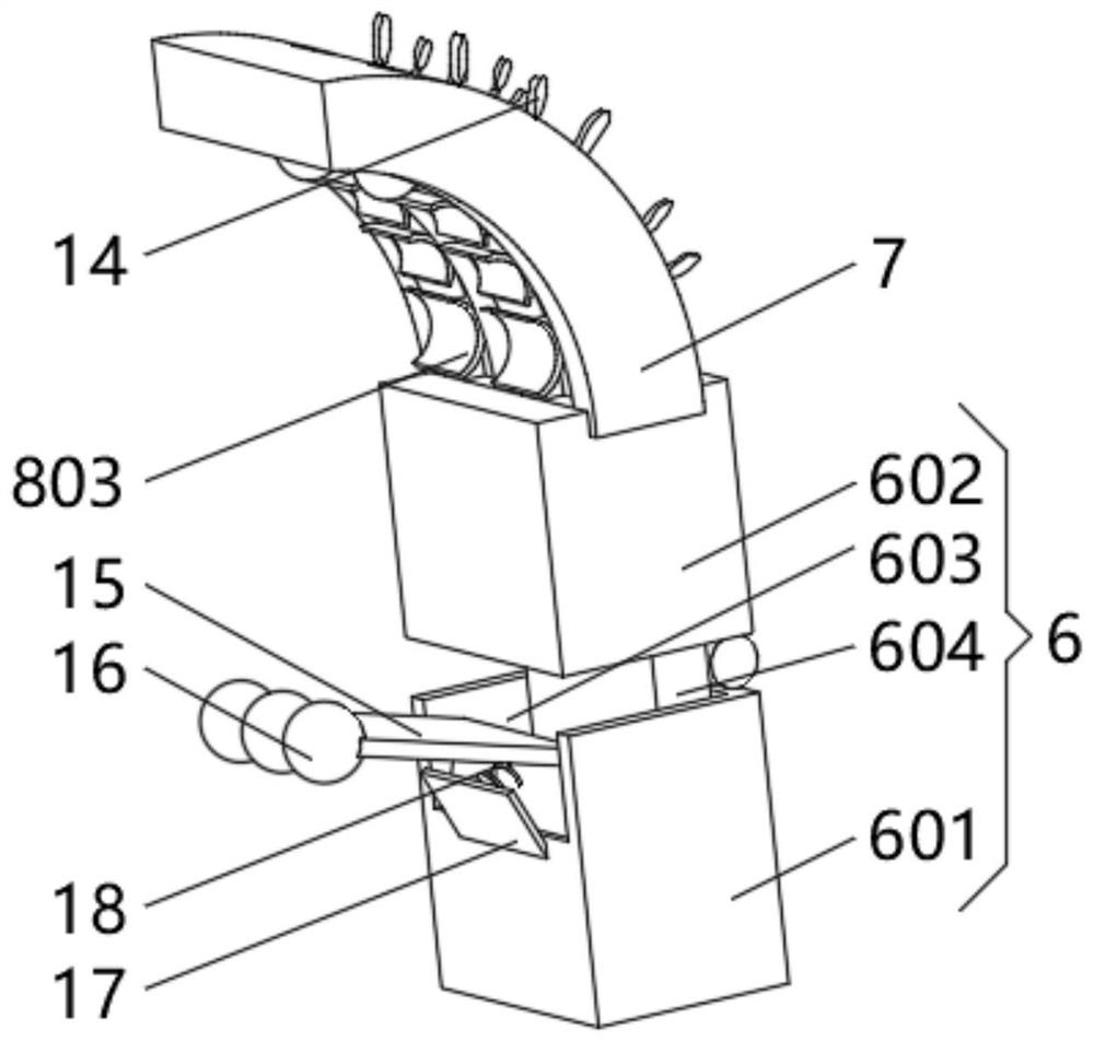
[0038] see Figure 1-4 , the present invention provides a technical solution: on the basis of Embodiment 1, a fitting device 8 is installed on one side of the lifting plate 7, and the fitting device 8 includes a fitting groove 801, and one side of the inner wall of the fitting groove 801 slides Connect to the limiting block 802, the end of the limiting block 802 extending to the outside of the fitting groove 801 is fixedly connected with the fitting sheet 803, and the inner wall side of the fitting groove 801 is located above the limiting block 802 and is slidably connected to the counterweight ball 804.
[0039] The side of the lifting plate 7 away from the fitting groove 801 is provided with a heat dissipation groove 12, the heat dissipation groove 12 communicates with the fitting groove 801, and the side of the limit block 802 away from the fitting piece 803 is symmetrically installed with a heat conduction rod 13, and the heat conduction rod 13 One end extending to the out...
Embodiment 3
[0042] see Figure 1-5 , the present invention provides a technical solution: on the basis of the second embodiment, the inner bottom of the guide groove 603 is rotatably connected with a folded plate 15, and the end of the folded plate 15 extending to the outside of the guide groove 603 is evenly equipped with a knocking ball 16, inclined One side of the rod 601 is fixedly connected with an angle plate 17 , and one side of the angle plate 17 is fixedly connected with the folding plate 15 through a swing spring 18 .
[0043] The knocking ball 16 includes a spherical shell 161. A knocking rod 162 is evenly installed on the outside of the spherical shell 161. One end of the knocking rod 162 extending to the inside of the spherical shell 161 is fixedly connected with a horizontal plate 163. One side of the horizontal plate 163 is passed through a vibrating spring. 164 is fixedly connected with the spherical shell 161, and a metal ball 165 is installed inside the spherical shell 1...
PUM
 Abstract
Description
Claims
Application Information
 - R&D
- Intellectual Property
- Life Sciences
- Materials
- Tech Scout
- Unparalleled Data Quality
- Higher Quality Content
- 60% Fewer Hallucinations
Browse by: Latest US Patents, China's latest patents, Technical Efficacy Thesaurus, Application Domain, Technology Topic, Popular Technical Reports.
© 2025 PatSnap. All rights reserved.Legal|Privacy policy|Modern Slavery Act Transparency Statement|Sitemap|About US| Contact US: help@patsnap.com


