
Machining method of journal type compressor blade

A processing method and compressor technology, applied in the field of mechanical processing, can solve the problems of many special fixtures and special measuring tools for processing equipment, long processing flow, out of tolerance and other problems

Active Publication Date: 2021-05-18
成都和鸿科技股份有限公司
View PDF16 Cites 2 Cited by
  • Summary
  • Abstract
  • Description
  • Claims
  • Application Information

AI Technical Summary

Problems solved by technology

[0003] 1. There are many machining processes, many processing equipment, special fixtures and special measuring tools are used, and the processing cycle is long;
[0004] 2. During machining, the six-point reference of the blank is transferred to the center hole at both ends, and the center hole will be deflected with the deformation of the blade during the machining process, and cannot be adjusted, resulting in out-of-tolerance finish machining dimensions;
[0005] 3. After the rough milling of the blade body, the large-end and small-end journals are fine-turned, resulting in insufficient rigidity of the blade as a whole and easy deformation, resulting in out-of-tolerance dimensions of the outer circle of the journal;
[0006] 4. The deformation of the blade after the fine milling of the blade body causes the coaxiality of the small end to be out of tolerance with respect to the large end;
[0007] 5. The processing process is long, there are many variables in the processing process, and the deformation is difficult to analyze and control

Method used


Image

  • Machining method of journal type compressor blade
  • Machining method of journal type compressor blade
  • Machining method of journal type compressor blade

Examples


Embodiment Construction

[0041] In order to make the purpose, technical solutions and advantages of the embodiments of the present invention clearer, the technical solutions in the embodiments of the present invention will be clearly and completely described below in conjunction with the drawings in the embodiments of the present invention. Obviously, the described embodiments It is a part of embodiments of the present invention, but not all embodiments. The components of the embodiments of the invention generally described and illustrated in the figures herein may be arranged and designed in a variety of different configurations.

[0042] Accordingly, the following detailed description of the embodiments of the invention provided in the accompanying drawings is not intended to limit the scope of the claimed invention, but merely represents selected embodiments of the invention. Based on the embodiments of the present invention, all other embodiments obtained by persons of ordinary skill in the art wi...


PUM


Abstract

The invention provides a machining method of a journal type compressor blade. The machining method comprises the following specific steps of S1, positioning and mounting a blank on a five-axis machining center by taking six positioning points on the blank as a positioning reference; S2, milling all shape elements of the large end to the size of a finished product, and obtaining an annular mounting groove and an angular mounting face; S3, milling all shape elements of the small end to the size of a finished product to obtain small end journal, and at the moment, converting the blank into an intermediate a; S4, positioning and mounting the intermediate a on the five-axis machining center with the outer circle of the annular mounting groove, the outer circle of the small-end journal and the angular mounting face as positioning references, and applying pretension force to the two ends of the intermediate a; and S5, milling the blade basin side and the blade back side of the blade body and other shape elements at the two ends of the blade body to the finished product size. According to the machining method, error accumulation caused by multiple times of reference conversion can be avoided, so that the deformation of the blades is concentrated, and the deformation of the blade in the machining process is controllable.

Description

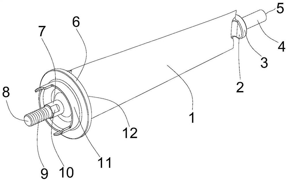
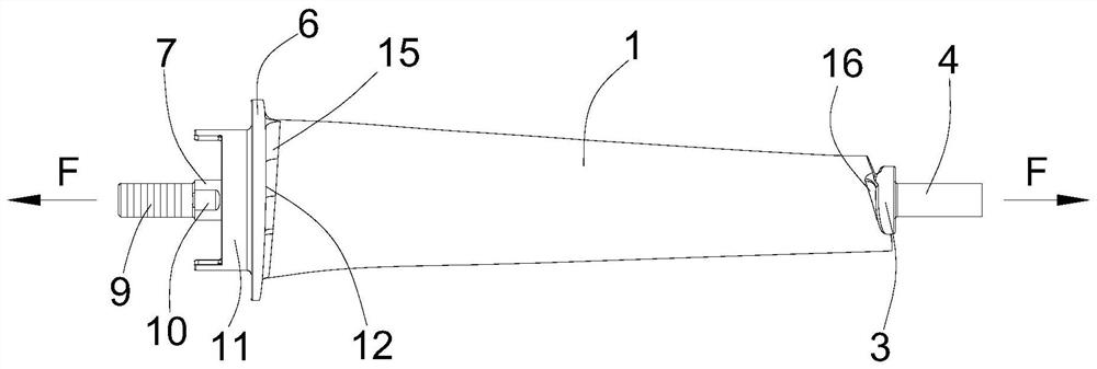
technical field [0001] The invention relates to the technical field of mechanical processing, in particular to a method for processing journal-type compressor blades. Background technique [0002] The blade structure of a certain type of compressor is as follows: figure 1 and figure 2 As shown, it consists of a large end journal 7, a small end journal 4, a large end mounting plate, a small end mounting plate, an annular mounting groove 11 and a blade body 1, and the large end journal 7 and the small end journal 4 are coaxial, The large-end journal 7 is distributed on the first end of the airfoil 1, the small-end journal 4 is distributed on the second end of the airfoil 1, the large-end mounting plate is located between the large-end journal 7 and the airfoil 1, and the small-end installation The plate is located between the journal 4 at the small end and the airfoil 1, and the annular mounting groove 11 is located between the journal 7 at the large end and the mounting pl...

Claims


Application Information

Patent Timeline
IPC IPC(8): B23C3/18
CPCB23C3/18
Inventor 朱宇叶华强何先东张爱民郑珂徐培江
Owner 成都和鸿科技股份有限公司
Learn More