Supercharge Your Innovation With Domain-Expert AI Agents!

Hydraulic retarder and vehicle

A hydraulic retarder and gearbox technology, applied in the direction of liquid resistance brakes, brake types, mechanical equipment, etc., can solve the problems that are not conducive to the fuel economy of the whole vehicle

Active Publication Date: 2021-05-18
FAW JIEFANG AUTOMOTIVE CO
View PDF25 Cites 2 Cited by
  • Summary
  • Abstract
  • Description
  • Claims
  • Application Information

AI Technical Summary

Problems solved by technology

When the hydraulic retarder is in the non-working state, the rotor stirs the air flow and acts on the stator blades, thereby generating no-load braking torque, which is not conducive to the fuel economy requirements of the vehicle

Method used


Image

  • Hydraulic retarder and vehicle
  • Hydraulic retarder and vehicle
  • Hydraulic retarder and vehicle

Examples


Embodiment Construction

[0034] In order to make the above objects, features and advantages of the present invention more comprehensible, specific implementations of the present invention will be described in detail below in conjunction with the accompanying drawings. In the following description, numerous specific details are set forth in order to provide a thorough understanding of the present invention. However, the present invention can be implemented in many other ways different from those described here, and those skilled in the art can make similar improvements without departing from the connotation of the present invention, so the present invention is not limited by the specific embodiments disclosed below.

[0035] In describing the present invention, it should be understood that the terms "center", "longitudinal", "transverse", "length", "width", "thickness", "upper", "lower", "front", " Back", "Left", "Right", "Vertical", "Horizontal", "Top", "Bottom", "Inner", "Outer", "Clockwise", "Counte...


PUM


Abstract

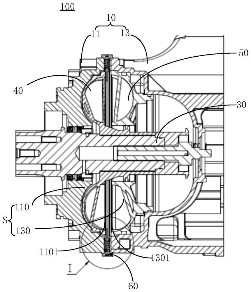
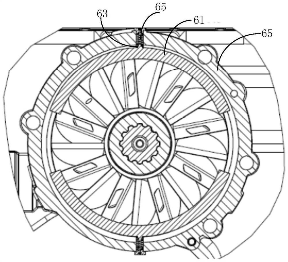
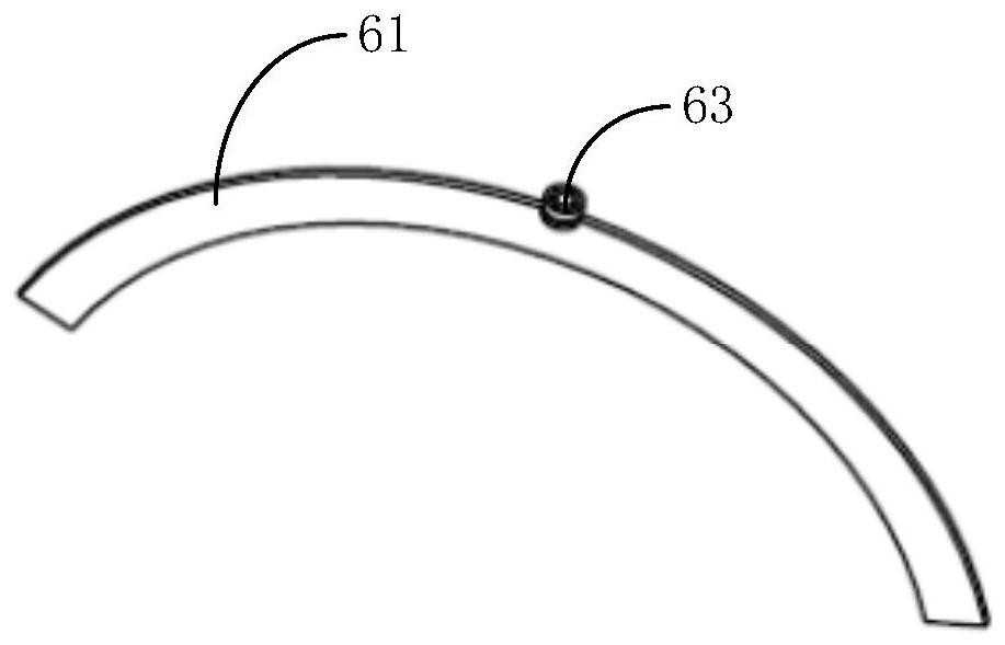
The invention relates to a hydraulic retarder and a vehicle. The hydraulic retarder comprises a shell with a working cavity, a gearbox output shaft axially arranged in the shell in a penetrating manner, a rotor arranged in the working cavity and connected with the gearbox output shaft, a stator fixed to the shell and located in the working cavity, and a turbulence structure mounted on the shell and telescopically arranged in the working cavity relative to the shell, wherein a spoiler is moved out of the working cavity when the hydraulic retarder is in a working state, and is returned to the working cavity when the hydraulic retarder is in a non-working state. The spoiler located in the working cavity is blocked between a rotor and a stator, and the spoiler only covers the outer edges, away from the center point, of the rotor and the stator in the radial direction. The hydrodynamic retarder stated in the application is favorable to reduction of a no-load braking torque generated by air stirring through the rotor in the non-working state, and the no-load loss of the hydrodynamic retarder is reduced.

Description

technical field [0001] The invention relates to the technical field of automobiles, in particular to a hydraulic retarder and a vehicle. Background technique [0002] The hydraulic retarder is a device that uses the damping effect of the oil flow to generate anti-drag torque on the vehicle. At present, it is often matched with the tractor on the heavy-duty truck to undertake the auxiliary braking function to ensure that the heavy-duty truck is in the long downhill process. Reduce the main braking action time, effectively guarantee the life of the main braking system and the safety of the vehicle. [0003] Among them, the main structure of the hydraulic retarder is the rotor and the stator. When the hydraulic retarder is in the working state, the oil enters the working chamber between the rotor and the stator, and the oil accelerates to rotate under the action of the rotor and impacts the stator, and then acts on the rotor in reverse after being impacted by the stator blades...

Claims


Application Information

Patent Timeline
IPC IPC(8): F16D57/02
CPCF16D57/02
Inventor 韩旭徐国林肇润东杨启张晓丽张樱玮王丽娜
Owner FAW JIEFANG AUTOMOTIVE CO
Features
  • R&D
  • Intellectual Property
  • Life Sciences
  • Materials
  • Tech Scout
  • Unparalleled Data Quality
  • Higher Quality Content
  • 60% Fewer Hallucinations
Learn More