Pile pulling device for water conservancy project

A technology for water conservancy projects and equipment, which is applied to foundation structure engineering, sheet pile walls, buildings, etc., can solve problems such as difficult to find in time, loose rudder, and reduce the clamping effect of splints in pile pulling equipment, so as to improve stability, The effect of improving reliability

Inactive Publication Date: 2021-05-25
刘学彦
View PDF6 Cites 2 Cited by
  • Summary
  • Abstract
  • Description
  • Claims
  • Application Information

AI Technical Summary

Problems solved by technology

[0005] In order to solve the above-mentioned technical problems, the present invention provides a pile-extracting equipment for water conservancy projects. The support structure at the bottom of the above-mentioned pile-extracting equipment is a support wheel. When the ground hardness at the bottom of the pile-extracting equipment is low, it is easy to make the bottom of the pile-extracting equipment The support wheel is sunk into the soil, which reduces the stability of the pile pulling equipment when pulling out piles. After the steering rudder in the above pile pulling equipment is fastened, due to the lack of an effective anti-loosening structure on the upper part of the steering rudder, when the pile locking device shakes frequently When the rudder is turned, it is easy to loosen the rudder, and once the rudder is loosened, the splint in the pile locking device will be loosened, thereby reducing the reliability of the pile pulling equipment when pulling out piles, and when the splint in the above pile pulling equipment When the clamping surface is severely worn, it is difficult for people to find it in time, which reduces the clamping effect of the splint in the pile pulling equipment

Method used


Image

  • Pile pulling device for water conservancy project
  • Pile pulling device for water conservancy project
  • Pile pulling device for water conservancy project

Examples


Embodiment

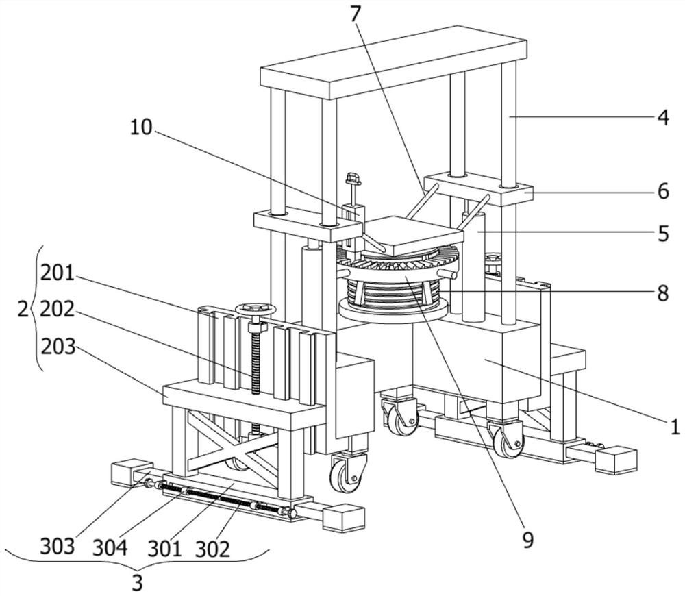
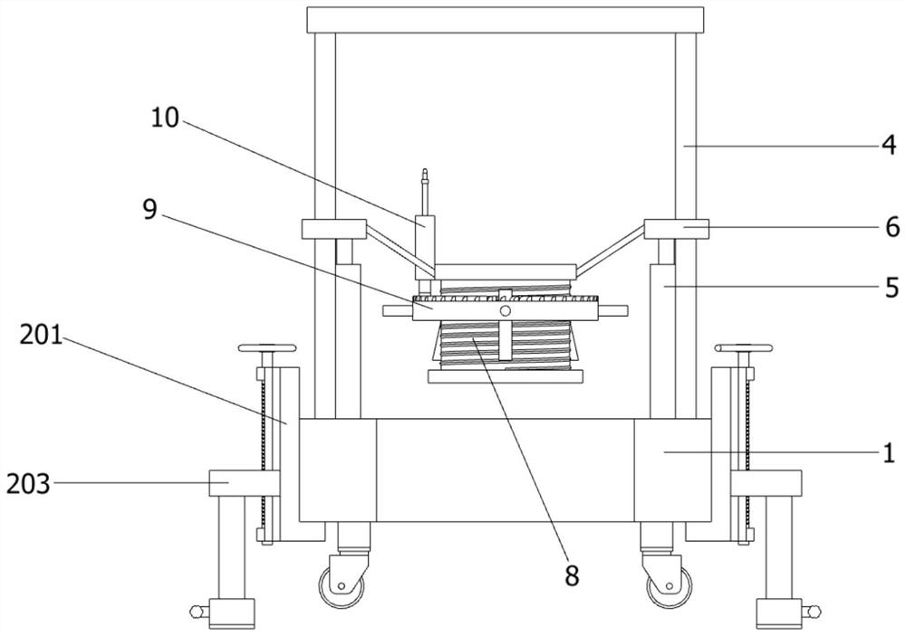
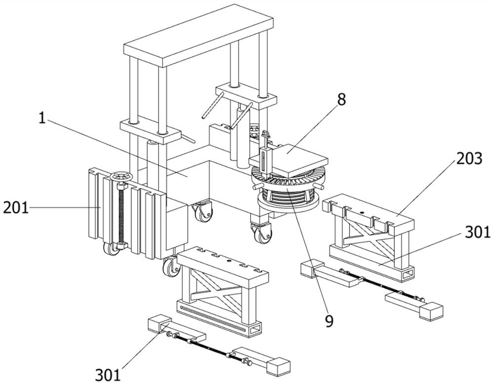
[0033] as attached figure 1 To attach Figure 8 Shown:

[0034] The present invention provides a pile pulling device for water conservancy projects, comprising: a body 1, a support mechanism 2 is provided on the left and right sides of the body 1, and the support mechanism 2 includes an L-shaped fixed plate 201, a support screw 202 and a sliding support plate 203, The L-shaped fixed plate 201 is fixedly connected to one side of the body 1, and the other side of the L-shaped fixed plate 201 is symmetrically provided with four T-shaped sliders, and the other side of the L-shaped fixed plate 201 passes through four T-shaped sliders. A sliding support plate 203 is slidably connected, and one side of the sliding support plate 203 is symmetrically provided with four T-shaped chutes slidingly connected with the T-shaped slider on the L-shaped fixed plate 201, and the other side of the L-shaped fixed plate 201 is The middle part is connected with a support screw 202 through two rota...


PUM


Abstract

The invention provides a pile pulling device for a water conservancy project, and belongs to the technical field of pile pulling device. The problems that after a steering gear in the pile pulling device is fastened, due to the fact that the upper portion of the steering gear lacks an effective anti-loosening structure, when a pile locking device shakes frequently, the steering gear is prone to loosening, and then the reliability of the pile pulling device during pile pulling is reduced are solved. The pile pulling device comprises a machine body, supporting mechanisms are arranged on the left side and the right side of the machine body correspondingly, and an extending supporting piece is arranged at the lower end of each supporting mechanism; and four supporting shafts are fixedly connected to the upper end face of the machine body in a bilateral symmetry mode. When the pile locking device shakes frequently, due to the fact that a triangular limiting block at the lower end of an anti-loosening sliding block is in close contact with the upper end face of the steering gear, then a circular bead limiting tooth is matched, so that the steering gear cannot rotate anticlockwise at the moment, the steering gear is not prone to loosening, a clamping plate in the pile locking device cannot be loosened, and then the reliability of the pile pulling device during pile pulling is improved.

Description

technical field [0001] The invention belongs to the technical field of pile pulling equipment, and more specifically relates to a pile pulling equipment for water conservancy projects. Background technique [0002] The hydraulic pile extractor is a pile machine that uses the power of the hydraulic cylinder to pull the I-beam (H-beam) out of the ground. The hydraulic pile extractor uses its pile clamp to clamp the pile head, and the hydraulic cylinder forces the pile clamp to push upward for a certain distance, and the pile is pulled out piece by piece. It is suitable for clay, sand or soil containing a small amount of gravel. Pull I-beam or section steel piles in the layer. [0003] For example, application number: CN201910756120.7 The present invention relates to the technical field of pile pulling equipment, and discloses a hydraulic pile pulling equipment, including a support shaft installed on the top of the machine body and an adjustment device set on the support shaft...

Claims


Application Information

Patent Timeline
Patent Type & Authority Applications(China)
IPC IPC(8): E02D9/02
CPCE02D9/02
Inventor 刘学彦
Owner 刘学彦
Why Eureka
Try Eureka