Supercharge Your Innovation With Domain-Expert AI Agents!

Automatic wall plastering machine

A wall plastering machine and automatic technology, applied in the direction of construction, building structure, etc., can solve the problems of heavy load-bearing, damage to the first card piece plastering machine head, affecting construction efficiency and plastering wall surface quality.

Pending Publication Date: 2021-05-25
唐志顺 +1
View PDF3 Cites 1 Cited by
  • Summary
  • Abstract
  • Description
  • Claims
  • Application Information

AI Technical Summary

Problems solved by technology

The defect of this patent is: in the plastering process, the first clamping part of the wall plastering machine head needs to press through the locking part of the lever part of the first locking device to pass through the first locking device smoothly, so that the wall plastering machine The head walks from the first left track to the third left track, and even if the first clip on the wall-wiping head does not press the blocking part of the lever of the first blocking device, the wall-wiping head will continue Rising, forcefully let the first clip pass through the first blocking device, damaging the first clip or even the wall mopping head
The defect of the present invention is: the left track and the right track can be folded by using the hinged structure. Although the structure is simple and the cost is low, due to its high height and heavy load, the hinged structure is easily damaged, deformed or even broken, and the stability is not high. , unsafe
This patent is driven by a hydraulic cylinder or an air cylinder. The disadvantages are that the structure is relatively complicated, the product cost is high, and the work is unstable, which affects the construction efficiency and the quality of the plastered wall.

Method used


Image

  • Automatic wall plastering machine
  • Automatic wall plastering machine
  • Automatic wall plastering machine

Examples


Embodiment 1

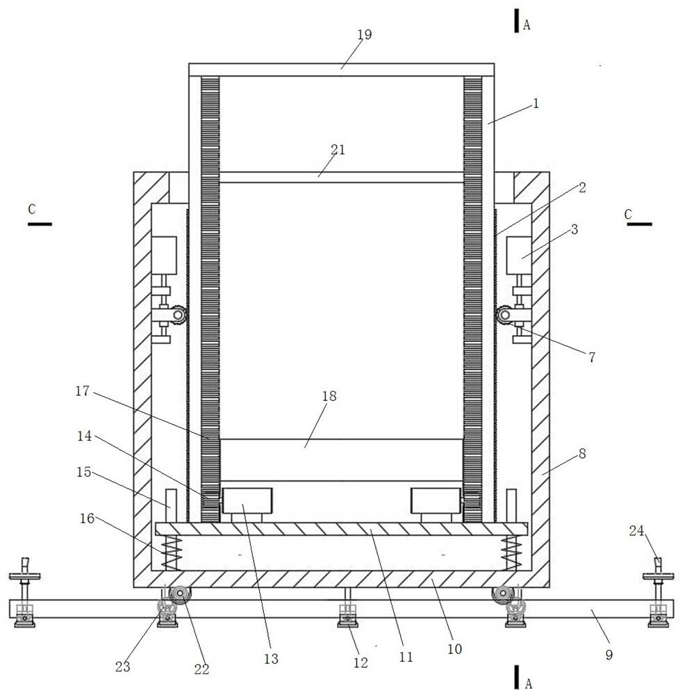
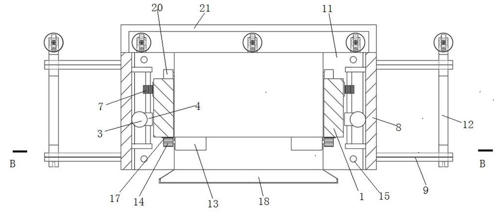
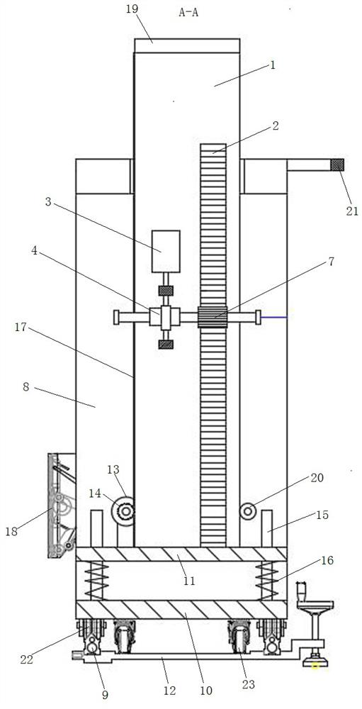
[0022]Such asfigure 1 -Figure 4As shown, an automatic wipe wall machine includes a rack, a wipe the wall base 18, and a wipeside seat drive mechanism including a support frame 8 and a liter 1, the wipe the wall base 18 is disposed at the lifting frame. 1. A lifting drive mechanism is provided between the support frame 8 and the lift frame 1, and the lifting drive mechanism drives the lift 1 to perform up and down movements on the support frame 8. The wipe wall base 18 is provided with a spheric wall base drive mechanism, and the wipe the wall base drive mechanism drives the wipe the wall base 18 to exercise up and down in the lift frame 1, thereby smearing the wall. The booster 1 is provided with a guide to move up and down the wall socket 18. The top plate 19 is connected at the top of the liter 1. In order to ensure the rigidity of the support frame 8, the top side portion of the support frame 8 has a connecting rod 21.

[0023]The lifting drive mechanism includes a first lifting mot...

Embodiment 2

[0030]The elevator drive mechanism includes a first lifting motor 3 and a first driving gear disposed on the left and right sides of the lift frame, symmetrically disposed on the first liter rack 2 on the left and right sides of the support rack. Other as in Example 1.

Embodiment 3

[0032]The rack includes a support frame 8 and two lifting frame 1, and a lift drive mechanism is provided between the support frame 8 and the liter 1 and between adjacent two-liter frames. Other as in Example 1.


PUM


Abstract

The invention discloses an automatic wall plastering machine. The automatic wall plastering machine comprises a rack, a wall plastering machine base and a wall plastering machine base driving mechanism. The rack comprises a supporting frame and at least one lifting frame, a lifting frame driving mechanism is arranged between the supporting frame and the lifting frame, and the lifting frame driving mechanism drives the lifting frame to move up and down on the supporting frame; and the wall plastering machine base is arranged on the lifting frame, and the wall plastering machine base driving mechanism drives the wall plastering machine base to move up and down on the lifting frame to conduct plastering on the wall. For a wall surface with a normal floor height, only one supporting frame and one lifting frame are adopted, the lifting frame driving mechanism drives the lifting frame to drive the wall plastering machine base to move up and down, and plastering on a lower wall surface can be completed; and then, the wall plastering machine base driving mechanism drives the wall plastering machine base to conduct plastering on upper and middle wall bodies. If a wall surface is too high, one supporting frame and more than two lifting frames can be adopted, and lifting frame driving mechanisms are arranged between the supporting frame and the lifting frames and between two adjacent lifting frames, so that no matter how high the wall surface is, plastering can be performed, and the application range is very wide.

Description

Technical field [0001] The invention relates to the field of construction, and specifically provides an automatic wall plastering machine. Background technique [0002] The wall plastering machine replaces the manual application of cement mortar on the wall and has the advantages of high efficiency, saving time and labor. Existing wall plastering machines are generally provided with a set of upright rails. Such a set of upright rails is usually composed of two parallel and vertical rails, called the left track and the right track. There are second racks on the left track and the right track respectively, and a driving gear is provided on the head of the wall plastering machine. Through the cooperation of the driving gear and the second rack, the wall plastering machine head can move up and down along the upright track, thereby Realize bottom-up plastering and top-down calendering functions. [0003] However, the length of the upright track of such a wall plastering machine...

Claims


Application Information

Patent Timeline
IPC IPC(8): E04F21/08
CPCE04F21/08
Inventor 唐志顺武国洋
Owner 唐志顺
Features
  • R&D
  • Intellectual Property
  • Life Sciences
  • Materials
  • Tech Scout
  • Unparalleled Data Quality
  • Higher Quality Content
  • 60% Fewer Hallucinations
Learn More