Optical fiber gyroscope convenient to mount

A fiber optic gyroscope and gyroscope technology, which is applied to Sagnac effect gyroscopes, gyroscope/steering sensing equipment, instruments, etc., can solve the problems of fiber optic gyroscope damage and complicated installation of fiber optic gyroscope installation structure, and achieves Fixed simple and convenient effects

Active Publication Date: 2021-05-25
TIANJIN NAVIGATION INSTR RES INST
View PDF11 Cites 1 Cited by
  • Summary
  • Abstract
  • Description
  • Claims
  • Application Information

AI Technical Summary

Problems solved by technology

[0003] However, the existing fiber optic gyroscope needs to be disassembled for replacement or maintenance during long-term use, and the fixed structure of the fiber optic gyroscope will cause damage during repeated disassembly and installation. The damage of the existing part of the fiber optic gyroscope installation structure is relatively cumbersome, so it is necessary to propose an easy-to-install fiber optic gyroscope

Method used


Image

  • Optical fiber gyroscope convenient to mount
  • Optical fiber gyroscope convenient to mount
  • Optical fiber gyroscope convenient to mount

Examples


Embodiment Construction

[0026] Embodiments of the present invention are described in further detail below in conjunction with the accompanying drawings:

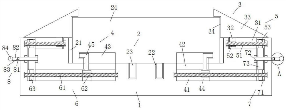
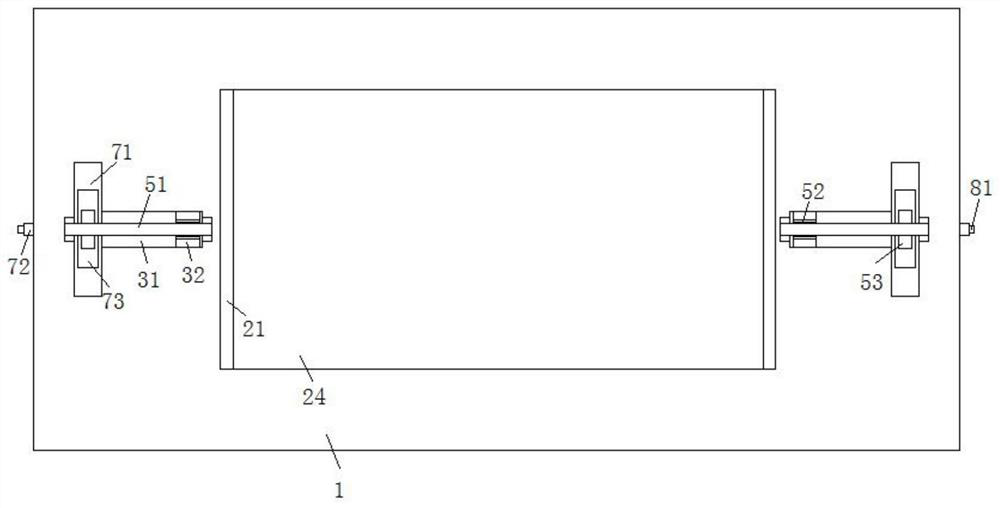
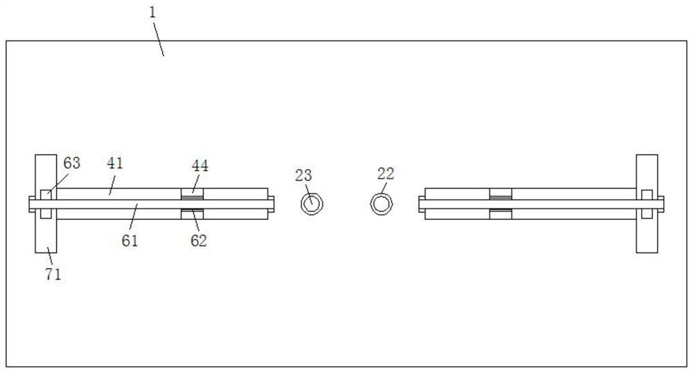
[0027] An easy-to-install fiber optic gyroscope, such as Figure 1 to Figure 7 As shown, it includes a mounting base 1, the upper surface of the mounting base 1 is provided with a gyroscope placement mechanism 2, and the upper surface of the mounting base 1 is symmetrically provided with two clamping mechanisms 3 with respect to the gyroscope placement mechanism 2, and the mounting base The inside of 1 is symmetrically provided with two fixing mechanisms 4 with respect to the gyroscope placement mechanism 2, a first conveying mechanism 5 is arranged inside the two clamping mechanisms 3, and a first conveying mechanism 5 is arranged inside the two fixing mechanisms 4. Two conveying mechanisms 6, two transmission mechanisms 7 are arranged symmetrically inside the installation seat 1, and the two transmission mechanisms 7 are respectively connected wi...


PUM


Abstract

The invention relates to an optical fiber gyroscope convenient to mount, which comprises a mounting seat, wherein a gyroscope placing mechanism is arranged on the upper surface of the mounting seat, two clamping mechanisms are symmetrically arranged on the upper surface of the mounting seat relative to the gyroscope placing mechanism, two clamping mechanisms are arranged in the mounting seat, two fixing mechanisms are symmetrically arranged in the mounting seat relative to the gyroscope placing mechanism, a first conveying mechanism is arranged in each of the two clamping mechanisms, a second conveying mechanism is arranged in each of the two fixing mechanisms, two transmission mechanisms are symmetrically arranged in the mounting seat, the two transmission mechanisms are connected with the first conveying mechanism and the second conveying mechanism correspondingly, and the ends, which are away from each other, of the two transmission mechanisms extend out of the mounting base and are provided with rotating mechanisms. The optical fiber gyroscope is simple and convenient, and the rotating rod is reversely rotated during disassembly.

Description

technical field [0001] The invention belongs to the technical field of fiber optic gyroscopes, in particular to a fiber optic gyroscope that is easy to install. Background technique [0002] Fiber optic gyro is a fiber optic angular velocity sensor based on the Sagnac effect. As a new type of all-solid-state inertial instrument, it has the advantages of no rotating parts, large angle measurement range, long life, high sensitivity and high reliability. It has become an inertial application field. The mainstream instrument has been widely used in aviation, aerospace, navigation and other fields. [0003] However, the existing fiber optic gyroscope needs to be disassembled for replacement or maintenance during long-term use, and the fixed structure of the fiber optic gyroscope will cause damage during repeated disassembly and installation. The damage of the existing part of the fiber optic gyroscope installation structure is relatively cumbersome, so it is necessary to propose...

Claims


Application Information

Patent Timeline
Patent Type & Authority Applications(China)
IPC IPC(8): G01C19/72
CPCG01C19/72G01C19/722
Inventor 宋超金利民宋魁孙晨尤磊
Owner TIANJIN NAVIGATION INSTR RES INST
Why Eureka
Try Eureka