Optical fiber vibration event identification method based on spectrum similarity

A fiber optic vibration and identification method technology, applied in the field of optical fiber vibration event identification based on spectral similarity, can solve problems such as false alarms, achieve the effects of reducing alarm time, simplifying calculation methods, and improving accuracy

Active Publication Date: 2021-05-25
江苏光为传感设备有限公司
View PDF5 Cites 2 Cited by
  • Summary
  • Abstract
  • Description
  • Claims
  • Application Information

AI Technical Summary

Problems solved by technology

[0004] However, due to the complex external environment, there will be a lot of false alarms. For example, many large vehicles pass by and generate a lot of vibration, which will lead to false alarms. At the same time, it is limited by the alarm time and other limitations.

Method used


Image

  • Optical fiber vibration event identification method based on spectrum similarity

Examples


Embodiment 1

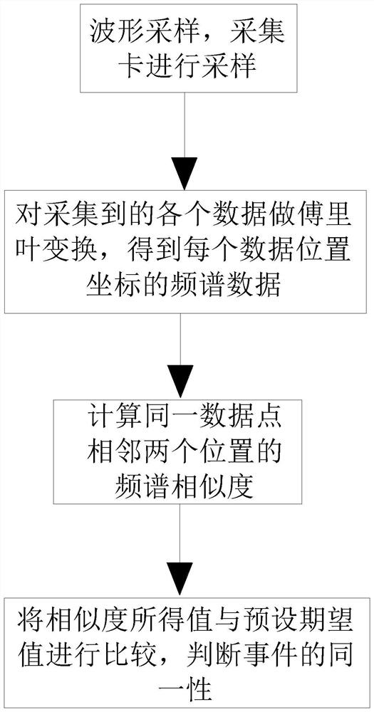
[0040] An optical fiber vibration event identification method based on spectral similarity. The expected value of the waveform similarity generated by optical fiber vibration is preset. Compare the waveform similarity with the preset expected value, and judge whether the alarm alarm is caused by the vibration caused by the external environment or the alarm caused by the internal failure of the optical fiber according to the difference;

[0041] The specific execution steps of the method are:

[0042] Step (1): The waveform sampling data of the initial waveform 1s is taken for analysis, and sampling is performed by the acquisition card during waveform sampling, wherein 4000 data are collected within 1 ms, and each data determines a data coordinate;

[0043] Step (2): On the basis of step (1), wherein, 1000 data groups are collected in every 1s, and the 1000 data groups are formed into a digital matrix of M*N=1000*4000, which is recorded as matrix N1, wherein, each The number o...

Embodiment 2

[0068] The norms of sequence X1 and sequence X2 are respectively recorded as norm(X1) and norm(X2), and the calculation rules of norm(X1) and norm(X2) are:

[0069] norm(X1)=√[(x11)2+(x12)2+(x13)2+...+(x1n)2];

[0070] norm(X2)=√[(x21)2+(x22)2+(x23)2+…+(x2n)2], at this time, the size of two frames of data is obtained.

[0071] In other embodiments, the similarity between sequence X1 and sequence X2 is recorded as S, and the calculation rule of similarity S is:

[0072] S=[sum(X1*X2) / (norm(X1) / norm(X2))]*100%;

[0073] Through the above calculation, we can get the similarity of the event spectrum at each position at two different times. If the similarity is less than 90%, it is considered that the two times are not the same behavior.

[0074] The working principle of the present invention is: by taking the waveform sampling data of the initial waveform 1s to analyze, wherein, 4000 data are collected within 1ms, each data determines a data coordinate, and 1000 data groups are ...


PUM


Abstract

The invention discloses an optical fiber vibration event identification method based on spectrum similarity. A waveform similarity expected value generated by optical fiber vibration is preset. When an optical fiber vibrates, waveform data of the optical fiber vibration is taken, and a waveform similarity degree is calculated according to frequency and amplitude data. By calculating the waveform similarity and comparing the waveform similarity with a preset expected value, whether the alarm is a false alarm caused by vibration generated by an external environment or an alarm caused by an internal fault of an optical fiber is judged according to a difference value. Through the calculation method, the waveform similarity can be quickly calculated, if the similarity reaches an expected value, the two waveform generation behaviors are considered to be consistent, the vibration behavior can be quickly determined, the calculation time is saved, meanwhile, the accuracy of behavior mode recognition is improved, the vibration event is quickly recognized by simplifying the calculation method. The alarm efficiency is improved by reducing the alarm time.

Description

technical field [0001] The invention relates to the field of optical fiber technology, in particular to a method for identifying optical fiber vibration events based on spectral similarity. Background technique [0002] Optical fiber sensor is a sensor that converts the state of the measured object into a measurable optical signal. The working principle of the fiber optic sensor is to send the light beam incident from the light source into the modulator through the optical fiber, and interact with the measured parameters outside the modulator to make the optical properties of the light such as light intensity, wavelength, frequency, phase, polarization state, etc. Changes to become a modulated optical signal, which is then sent to an optoelectronic device through an optical fiber, and the measured parameters are obtained after being demodulated. [0003] The light beam is introduced through the optical fiber, and then emitted after passing through the modulator. The role of...

Claims


Application Information

Patent Timeline
Patent Type & Authority Applications(China)
IPC IPC(8): G06K9/00G06K9/62G06F17/18G06F17/14
CPCG06F17/18G06F17/14G06F2218/10G06F18/22
Inventor 陈凯
Owner 江苏光为传感设备有限公司
Why Eureka
Try Eureka