An intelligent fire protection system
A fire-fighting system and intelligent technology, applied in fire rescue and other directions, can solve the problems of limited length of water pipes of fire-fighting devices, inconvenient adjustment of water spraying angle of fire-fighting devices, and inability to implement fire extinguishing in the absence of people, etc., to achieve water spraying The effect of easy adjustment of direction and angle
- Summary
- Abstract
- Description
- Claims
- Application Information
AI Technical Summary
Problems solved by technology
Method used
Image
Examples
Embodiment 1
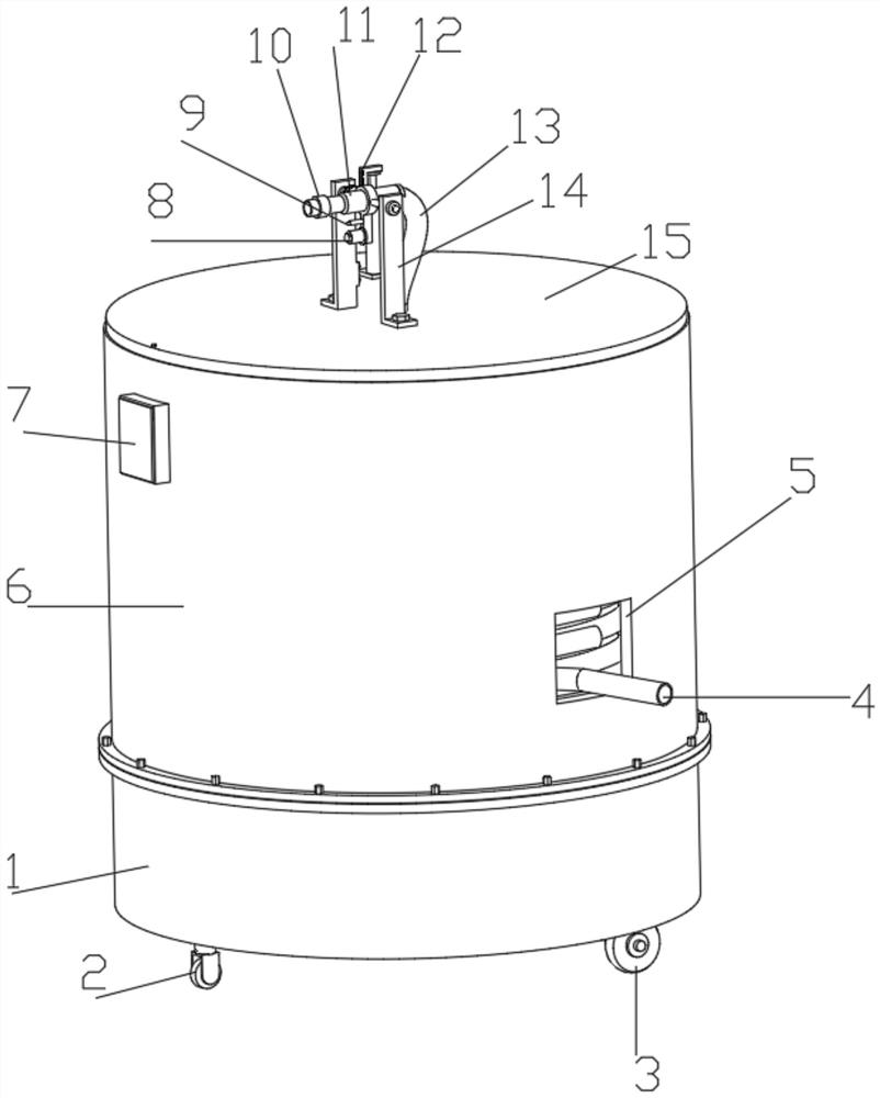
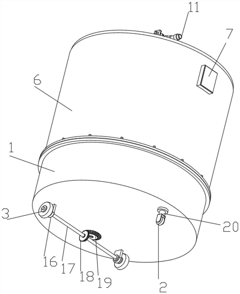
[0031] Such as figure 1 , 2 , A kind of intelligent fire protection system shown in 3, 4, 5, comprises lower housing 1 and controller 39, the bottom of lower housing 1 is connected with the mobile structure that is used for moving, and mobile structure comprises guiding wheel 2, driving wheel 3, Straight block 16, the first rotating shaft 17, the first bevel gear 18, the second bevel gear 19, the first drive motor 20 and the third drive motor 34, the bottom of the output end of the first drive motor 20 is fixedly connected with a guide for guiding Wheel 2, the lower housing 1 is symmetrically fixedly connected with a straight block 16 on the rear side of the guide wheel 2, and the straight block 16 is rotatably connected with a first rotating shaft 17 through a fixedly connected bearing, and the outer end of the first rotating shaft 17 is fixedly connected with a drive Wheel 3, the bottom of the driving wheel 3 is flush with the bottom of the guide wheel 2, the driving wheel ...
Embodiment 2
[0033] Embodiment 2 is a further improvement to Embodiment 1.
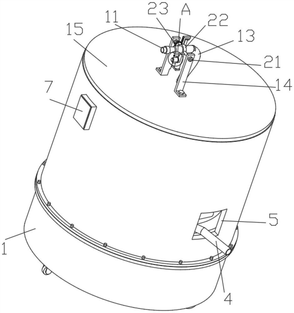
[0034] Such as figure 1 , 5 , 6, and 7, the top of the lower housing 1 is fixedly connected with the upper housing 6 through fixing bolts, and the upper housing 6 is connected with a winding structure for winding. The winding structure includes a water inlet hose 4, a Volume hole 5, hollow shaft 28, U-shaped plate 30, second bearing 31, turbine 32, second driving motor 33, worm screw 37 and winding roller 38, the bottom of U-shaped plate 30 is fixedly installed with the second drive through the mounting plate Motor 33, the output end of the second driving motor 33 is fixedly connected with a worm screw 37, the middle end of the lateral part of the U-shaped plate 30 is fixedly connected with the outer ring outer wall of the second bearing 31, and the inner ring inner wall of the second bearing 31 is fixedly connected with Hollow rotating shaft 28, the bottom of hollow rotating shaft 28 is fixedly connected with t...
Embodiment 3
[0036] Embodiment 3 is a further improvement to Embodiment 1.
[0037] Such as figure 1 , 3 , 5, 6, 8, 9, and 10, the top of the hollow rotating shaft 28 is connected with a multi-directional water spray structure for multi-directional water spray, and the multi-directional water spray structure includes electromagnetic valve 10, water spray pipe 11, L-shaped teeth Plate 12, middle hose 13, L-shaped plate 14, top plate 15, second rotating shaft 21, mounting ring 22, first gear ring 23, straight pipe 24, electric push rod 25, first bearing 26, second gear ring 27. The sealed bearing 29, the third ring gear 35 and the fourth drive motor 36, the output end of the fourth drive motor 36 is fixedly connected with the third ring gear 35, the third ring gear 35 is engaged with the second ring gear 27, the The top plate 15 is fixedly connected to the second ring gear 27, and there is a straight pipe 24 in the straight hole at the middle end of the top plate 15. The bottom of the stra...
PUM
 Abstract
Description
Claims
Application Information
 - R&D
- Intellectual Property
- Life Sciences
- Materials
- Tech Scout
- Unparalleled Data Quality
- Higher Quality Content
- 60% Fewer Hallucinations
Browse by: Latest US Patents, China's latest patents, Technical Efficacy Thesaurus, Application Domain, Technology Topic, Popular Technical Reports.
© 2025 PatSnap. All rights reserved.Legal|Privacy policy|Modern Slavery Act Transparency Statement|Sitemap|About US| Contact US: help@patsnap.com


