
Building aggregate multi-stage screening equipment for buildings

A technology for building aggregates and screening equipment, which is applied in sieves, separation of solids from solids by air flow, and solids separation, etc., can solve the problems of not being able to automatically transfer aggregates, labor-intensive, time-consuming, etc.

Active Publication Date: 2021-05-28
无锡市第五建筑工程有限公司
View PDF8 Cites 0 Cited by
  • Summary
  • Abstract
  • Description
  • Claims
  • Application Information

AI Technical Summary

Problems solved by technology

[0004] In order to overcome the disadvantages that the aggregate screening equipment currently on the market is labor-intensive and time-consuming, cannot automatically transfer aggregates, and has poor screening effects, the technical problem of the present invention is to provide a time-saving, labor-saving, high-practicability, Multi-stage screening equipment for building aggregates with good screening effect

Method used


Image

  • Building aggregate multi-stage screening equipment for buildings
  • Building aggregate multi-stage screening equipment for buildings
  • Building aggregate multi-stage screening equipment for buildings

Examples


Embodiment 1

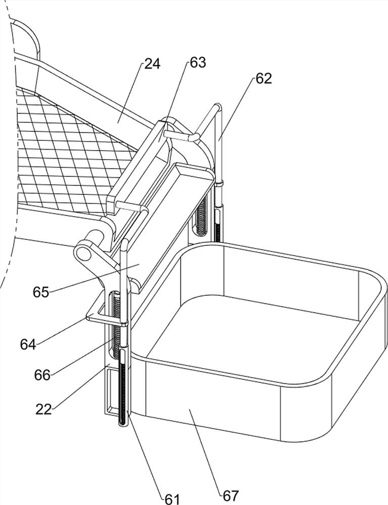
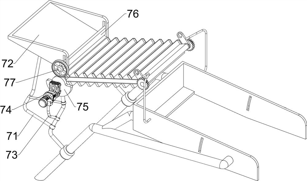
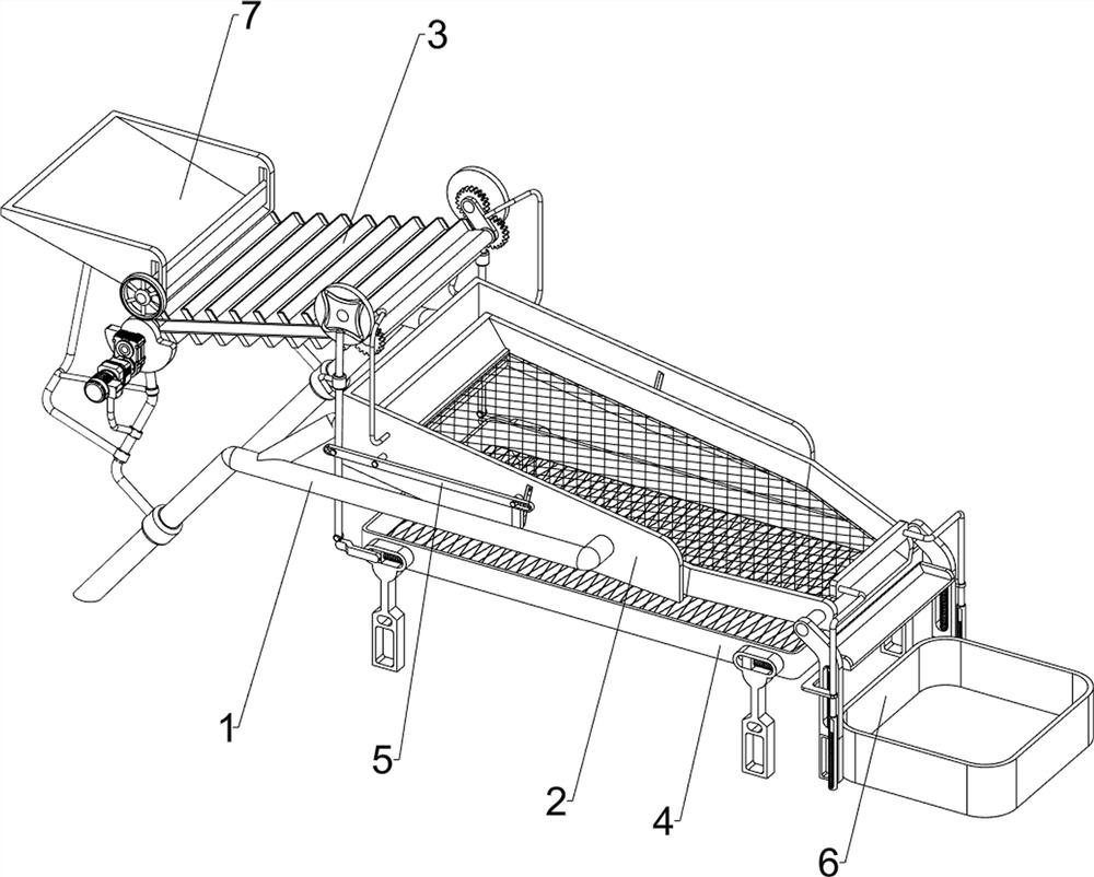
[0064] A multi-stage screening equipment for building aggregates for construction, such as figure 1 As shown, it includes a bracket 1 , a screening mechanism 2 and a delivery mechanism 3 , the bracket 1 is provided with a screening mechanism 2 , there are multiple brackets 1 , and a delivery mechanism 3 is connected between the screening mechanism 2 and the bracket 1 .

[0065] Such as figure 2 As shown, the screening mechanism 2 includes a placement plate 21, a first mounting plate 22, a first rotating shaft 23 and a first screen 24, and a placement plate 21 is arranged between the brackets 1 on the left side. Through holes 25, the first mounting plate 22 is installed on the bracket 1 on the right side, the first mounting plate 22 is connected with the first rotating shaft 23 in a rotational manner, and the first screen 24 is arranged between the first rotating shaft 23, The first screen 24 is slidingly engaged with the through hole 25 .

[0066] Such as image 3 As shown...

Embodiment 2

[0069] On the basis of Example 1, such as Figure 4 As shown, it also includes a fine screen mechanism 4, which includes a third mounting plate 41, a slide block 42, a first spring 43, a second screen cloth 44 and a push rod 45, and the bottom of the first screen cloth 24 is uniform Four third mounting plates 41 are placed, and sliders 42 are slidably arranged on the third mounting plates 41. First springs 43 are connected between the sliders 42 and the third mounting plates 41, and the sliders 42 are connected to each other. A second screen cloth 44 is arranged, and a push rod 45 is provided on the outside of the left slide block 42 .

[0070] The aggregate passing through the first sieve 24 will fall on the second sieve 44, and the staff can push the push rod 45 to the right, and the push rod 45 moves to the right to drive the left slide block 42 to move to the right, thereby the left The first spring 43 on the side is compressed, and the left slider 42 moves to the right t...


PUM


Abstract

The invention relates to screening equipment, in particular to building aggregate multi-stage screening equipment for buildings. The building aggregate multi-stage screening equipment for the buildings saves time and labor and is high in practicability and good in screening effect. According to the technical scheme, the building aggregate multi-stage screening equipment for the buildings comprises a support and a conveying mechanism, wherein a screening mechanism is arranged on the support; and the conveying mechanism is connected between the screening mechanism and the support. Through the screening mechanism and the conveying mechanism, aggregate to be screened can be continuously conveyed to a first screen, and then screening work can be conducted through the first screen; and through a fine screening mechanism, the screened aggregate can be subjected to secondary screening.

Description

technical field [0001] The invention relates to a screening device, in particular to a multi-stage screening device for construction aggregates. Background technique [0002] Aggregate is a granular loose material that acts as a skeleton or filling in concrete. As the main raw material in concrete, aggregate acts as a skeleton and support in buildings. There are two types of fine aggregate and coarse aggregate. The size is different. In order to ensure the quality of concrete, aggregates need to be screened before concrete. Manual screening of aggregates is time-consuming and labor-intensive. Therefore, machine-assisted screening is required. The aggregate screening equipment currently on the market is more labor-intensive and time-consuming. The aggregate cannot be automatically transferred, and the screening effect is not good. [0003] Therefore, there is an urgent need to develop a multi-stage screening device for building aggregates that saves time and effort, has high...

Claims


Application Information

Patent Timeline
IPC IPC(8): B07B9/00B07B1/28B07B1/42B07B1/46B65G69/12
CPCB07B9/00B07B1/28B07B1/42B07B1/46B65G69/12Y02W30/91
Inventor 林有连
Owner 无锡市第五建筑工程有限公司
Learn More