
Large current plane contact conductive device

A technology of plane contact and conductive device, applied in the direction of measuring device, measuring device shell, measuring electricity, etc., can solve the problems of affecting the data reading of the detection equipment, affecting the detection accuracy, reducing the over-current capability, etc., achieving a simple structure, increasing Effective contact area and the effect of improving test accuracy

Active Publication Date: 2019-02-22
深圳市瑞能创新科技有限公司
View PDF8 Cites 0 Cited by
  • Summary
  • Abstract
  • Description
  • Claims
  • Application Information

AI Technical Summary

Problems solved by technology

The test plane and the measured plane are not parallel, so the effective contact area will be much smaller than the theoretical coverage area, which increases the contact impedance and reduces the overcurrent capability, which affects the accuracy of the detection and the reading of the data by the detection equipment.

Method used


Image

  • Large current plane contact conductive device
  • Large current plane contact conductive device

Examples


Embodiment Construction

[0021] In order to make the object, technical solution and advantages of the present invention clearer, the present invention will be further described in detail below in conjunction with the accompanying drawings and embodiments. It should be understood that the specific embodiments described here are only used to explain the present invention, not to limit the present invention.

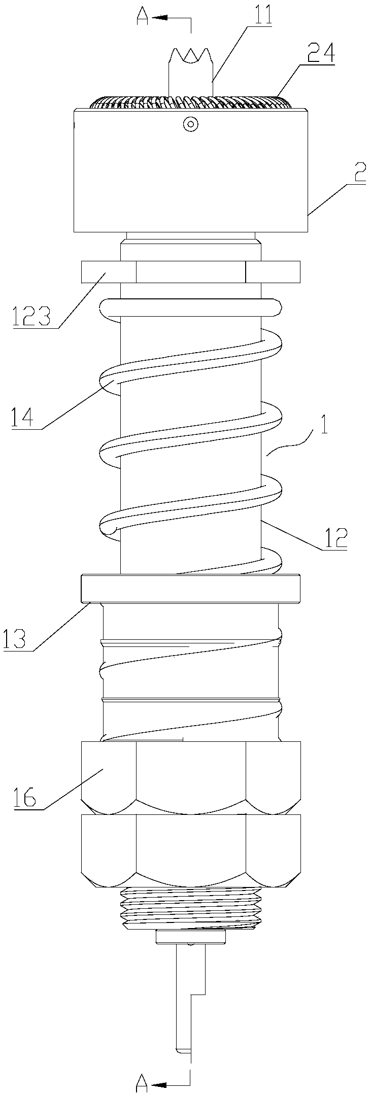
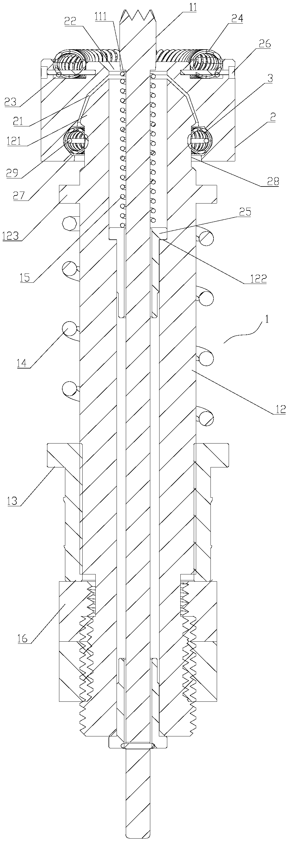
[0022] Such as Figure 1-2 As shown, the large current planar contact conductive device provided by the embodiment of the present invention includes a probe body 1. The probe body 1 includes a voltage probe 11 and a needle bar 12. The needle bar 12 is sleeved on the voltage probe 11, and the needle The insulated connection between the rod 12 and the voltage probe 11; also includes the contact head 2, the contact head 2 is provided with a spherical groove 21 and the first cavity 22, the front end of the needle rod 12 is provided with a ball joint 121, and the ball joint 121 is limited It is located...


PUM


Abstract

The invention discloses a heavy current plane contact conductive device which comprises a probe main body, wherein the probe main body comprises a voltage probe and a probe rod; the probe rod is sleeved on the voltage probe; the probe rod and the voltage probe are in insulating connection with each other; the heavy current plane contact conductive device further comprises a contact head; a spherical groove and a first chamber are arranged on the contact head; a spherical joint is arranged at the front end of the probe rod; the spherical joint is limited in the spherical groove and is capable of rotating relative to the spherical groove along a three-dimensional direction; the front end of the voltage probe is penetrated through the first chamber and extends out of the contact head; the peripheral size of the first chamber is more than the peripheral size of the corresponding part of the voltage probe located in the first chamber; a connecting spring is arranged between the contact head and the spherical joint and is used for realizing the conductive connection between the contact head and the spherical joint; the moveable connection capable of rotating along the three-dimensional direction is formed between the probe main body and the contact head; the contact head is capable of automatically rotating and calibrating, is capable of aligning a test surface of a battery and increasing the test precision and is suitable for heavy current test.

Description

technical field [0001] The invention belongs to the field of battery testing equipment, and in particular relates to a large-current planar contact conductive device. Background technique [0002] With the outbreak of the new energy vehicle industry, power batteries are the core components of new energy vehicles, and their electrical performance and safety performance directly affect the application and promotion of electric vehicles. Among them, in the production and manufacturing process, the formation, capacity separation and subsequent electrical performance and safety performance testing of power batteries are inseparable from testing equipment. The conductive device used by the testing equipment to fix the battery to be tested affects whether the testing equipment can accurately read the test data of the power battery. In the power battery, the pole only has a small external contact area. How to use this limited contact area without affecting the accurate and stable r...

Claims


Application Information

Patent Timeline
Patent Type & Authority Patents(China)
IPC IPC(8): G01R31/385G01R1/04
CPCG01R1/0416G01R31/385
Inventor 李莉
Owner 深圳市瑞能创新科技有限公司
Learn More