
Air vent mechanism for improving injection molding quality

A porosity and quality technology, applied in the field of porosity mechanisms to improve injection molding quality, can solve problems such as sticking together, difficult to clean, clogging, etc.

Pending Publication Date: 2021-05-28
武汉圣维林环节能技术有限公司
View PDF3 Cites 0 Cited by
  • Summary
  • Abstract
  • Description
  • Claims
  • Application Information

AI Technical Summary

Problems solved by technology

In the mold design, the exhaust position is often simulated by software, but in reality, the exhaust position will be slightly offset; there are more vent holes at the simulated exhaust position to facilitate exhaust; but the vent hole is increased It is easy to cause thin plastic strips with redundant air holes on the surface of the molded product, that is, the air vents are injected and blocked; after the mold is opened, the plastic in the air vents sticks to the product, and it is not easy to clean up later

Method used


Image

  • Air vent mechanism for improving injection molding quality
  • Air vent mechanism for improving injection molding quality
  • Air vent mechanism for improving injection molding quality

Examples


Embodiment Construction

[0038] The specific implementation manners of the present invention will be further described in detail below in conjunction with the accompanying drawings and embodiments. The following examples or drawings are used to illustrate the present invention, but not to limit the scope of the present invention.

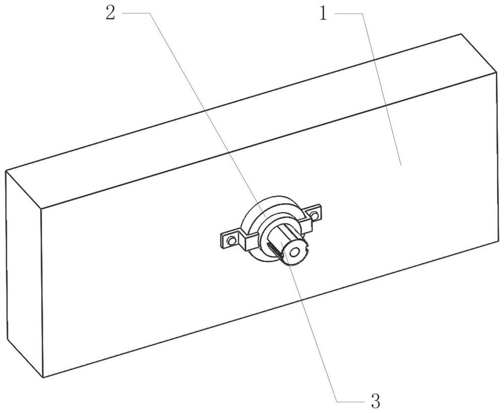
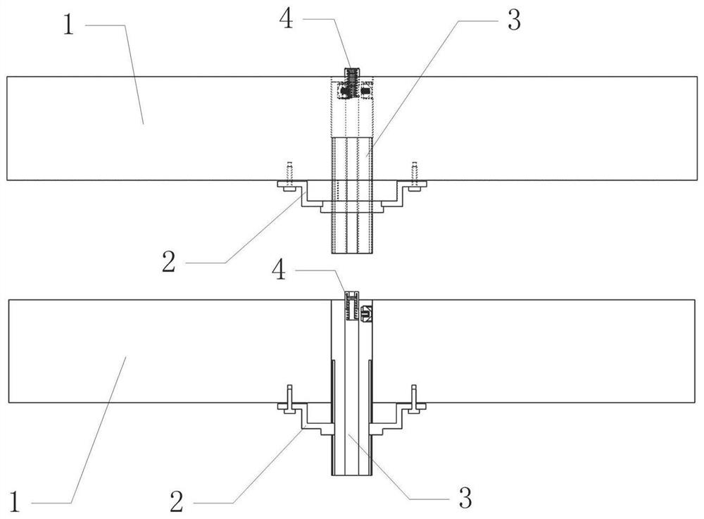
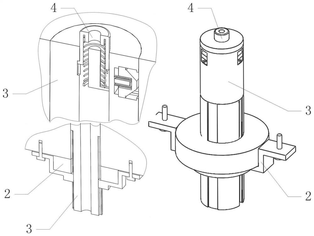
[0039] Such as figure 1 , 2 , 3, it includes exhaust intubation 3, switch valve 4, tightening mechanism 2, where as Figure 8 As shown, the outer circular surface of one end of the exhaust cannula 3 is uniformly provided with three mounting grooves 16 in the upper direction, and the outer circumferential surface of the other end of the exhaust cannula 3 has external threads 18, and the external threads 18 have an included angle of 30-degree thread notch 21 area; exhaust intubation 3 has two chute 19 symmetrically on the outer circular surface of one end of external thread 18; switch valve 4 is installed on exhaust intubation 3 and has installation groove 16 At one end, t...


PUM

PropertyMeasurementUnit
angleaaaaaaaaaa

Abstract

The invention belongs to the technical field of mold air vent insertion, and particularly relates to an air vent mechanism for improving injection molding quality. The air vent mechanism comprises an air venting insertion pipe, a switch valve and a tightening mechanism. The equipment designed according to the invention is capable of adjusting insertion depths according to different thicknesses of mold plates, and ensuring that the air venting insertion pipe can be used for the mold plates within a certain thickness range. In the equipment designed according to the invention, the air venting insertion pipe with a moderate length is manufactured and selected according to the thicknesses of the mold plates commonly used in practical application. In addition, the equipment designed according to the invention is also suitable for molds of which specific structures inside the molds and the depths of air vents can not be observed from the outside. The air vent mechanism is relatively convenient to use. After the installation of the equipment, the end, equipped with a valve sleeve, of the air venting insertion pipe is flush with the end surface, positioned on the inner end of the corresponding mold, of the corresponding air vent, so that protrusions and the like can be avoided.

Description

[0001] Technical field [0002] The invention belongs to the technical field of mold air hole insertion, and in particular relates to an air hole mechanism for improving injection molding quality. Background technique [0003] In the injection molding process, there is often more than one injection gate. In the process of multi-gate simultaneous injection molding, the air bubbles in the mold need to be discharged through the pores, but the temperature and pressure of the injection molding are slightly different, which will cause the final air bubbles to be discharged. The change of air position, that is, the reasonable arrangement of air hole position is very important. In the mold design, the exhaust position is often simulated by software, but in reality, the exhaust position will be slightly offset; there are more vent holes at the simulated exhaust position to facilitate exhaust; but the vent hole is increased It is easy to cause thin plastic strips formed by injection mo...

Claims


Application Information

Patent Timeline
Patent Type & Authority Applications(China)
IPC IPC(8): B29C45/34
CPCB29C45/34
Inventor 王小娥王海兰
Owner 武汉圣维林环节能技术有限公司
Learn More