Unlock instant, AI-driven research and patent intelligence for your innovation.
Method for measuring spatial displacement of building based on spatial position relation of coordinate points
What is Al technical title?
Al technical title is built by PatSnap Al team. It summarizes the technical point description of the patent document.
A technology of spatial position and spatial displacement, applied in the direction of measuring devices, mechanical measuring devices, mechanical devices, etc., to achieve the effect of reducing engineering risks
Inactive Publication Date: 2021-05-28
CENT & SOUTHERN CHINA MUNICIPAL ENG DESIGN & RES INST CO LTD
View PDF8 Cites 1 Cited by
Summary
Abstract
Description
Claims
Application Information
AI Technical Summary
This helps you quickly interpret patents by identifying the three key elements:
Problems solved by technology
Method used
Benefits of technology
Problems solved by technology
However, this measurement method can only measure the distance deviation of a certain position on a straight line, such as settlement and inclination, and the displacement of buildings and structures is mostly spatial displacement. Therefore, how to use existing measurement tools to cooperate with better measurement methods It is necessary to measure the spatial displacement of buildings and structures
Method used
Image
Click on the blue label to locate the original text in one second.
Reading with bidirectional positioning of images and text.
Examples
Embodiment 1
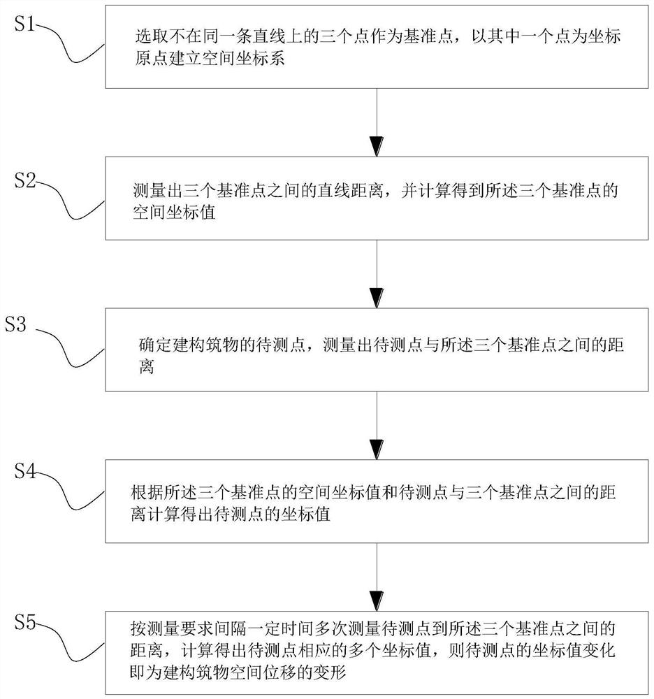
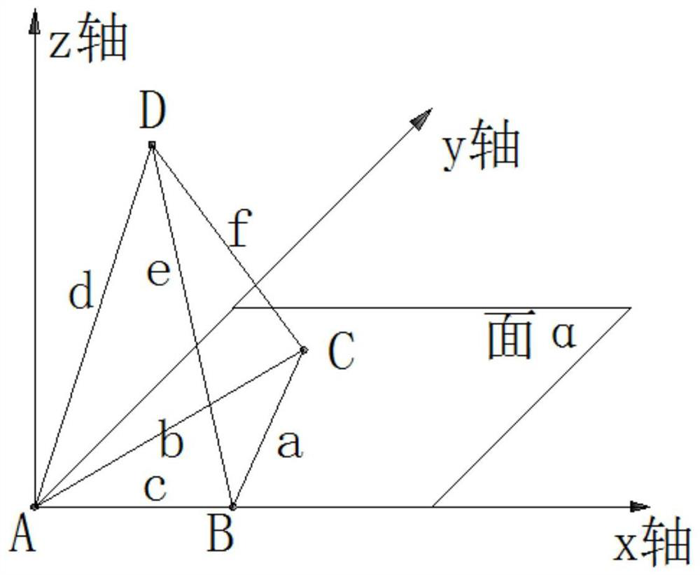
[0032]Combinefigure 1 ,2As shown, the method of measuring the spatial displacement of the measurement of the present invention is used to measure the deformation of the buildings of the new building. The specific process is as follows:
[0033](1) Space geometry mentioned that two points are determined a straight line, not in the same straight line, one plane, such asfigure 2 As shown, the three points A, B, C do not in the same straight line are selected as the measurement reference point, the A, B, and C. The three points are fixed, and it is fixed without moving, and does not change as the settlement or deformation of the constructive; Points A, B, and C determine a plane α, with a point as the origin, the straight line AB is the X-axis direction, and the straight line perpendicular to the straight line AB is the Y-axis direction, and the X-axis, the positive direction of the Y-axis is directed toward the direction. The normal direction of the plane α establishes a spatial coordinat...
Embodiment 2
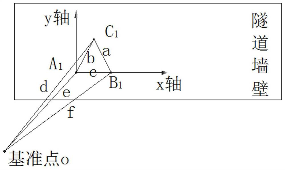
[0046]Combinefigure 1 ,3, 4, the method of measuring the spatial displacement of the measurement of the measurement of the present invention is used to measure the sink and peripheral convergence deformation of the tunnel vault, and the basic principles and steps of the present invention and the first embodiment of the new build building buildings. Basically, the difference is that in this embodiment, a reference point O point is added outside the tunnel for reviewing A.1, B1, C1Three points change, here A1, B1, C1Three points are equivalent to the A, B, C point in Example 1, just for the sake of different, according to A1, B1, C1The spatial coordinate system established by the three points is likeimage 3 Indicated.
[0047]Further, such asFigure 4 As shown, the measuring point D is arranged in the same tunnel in the same tunnel with the reference point A1, B1, C1.1Add to measure the sinking of the vault, arrange E1Point is used to measure the periphery convergence, and the measurement...
PUM
Abstract
The invention provides a method for measuring the spatial displacement of a building based on the spatial position relationship of coordinate points. The method carries out the real-time three-dimensional space measurement of a designated point of the building by using the three-dimensional coordinate spatial relationship of three reference points and combining with a measurement tool. By adopting the measuring method disclosed by the invention, the spatial displacement change of the specified point on the building can be more effectively and intuitively monitored, so that the three-dimensional spatial displacement of the building is monitored, more powerful data support is provided for construction and maintenance, an engineering constructor and an operation maintenance party are helped to make more favorable judgment on the health condition of the building, and the engineering risk can be effectively reduced and is prevented.
Description
Technical field[0001]The present invention relates to the field of engineering construction monitoring, and in particular, a method of measuring the spatial displacement of the construction of the constructive site based on the positional relationship between the coordinate point spatial position.Background technique[0002]With the continuous development of my country's infrastructure industry, the construction of buildings such as deep base pit, high-side slope, bridge tunnel is increasing. At present, for the deformation measurement of the construction, generally measurement is mostly the displacement parameters of a particular point on the construction of the building, mainly using instruments such as levels, all-station, and other instruments. However, this measurement method can only measure the distance deviation of a location point on the straight line, such as settlement, tilting, and the displacement of the built-in is more spatial displacement, so how to use the existing me...
Claims
Application Information
Patent Timeline
Application Date:The date an application was filed.
Publication Date:The date a patent or application was officially published.
First Publication Date:The earliest publication date of a patent with the same application number.
Issue Date:Publication date of the patent grant document.
PCT Entry Date:The Entry date of PCT National Phase.
Estimated Expiry Date:The statutory expiry date of a patent right according to the Patent Law, and it is the longest term of protection that the patent right can achieve without the termination of the patent right due to other reasons(Term extension factor has been taken into account ).
Invalid Date:Actual expiry date is based on effective date or publication date of legal transaction data of invalid patent.
Patent Type & Authority Applications(China)
IPC IPC(8): G01B5/004
CPCG01B5/004
Inventor 罗浩张美聪何振华谢首祥刘莉郑东东
Owner CENT & SOUTHERN CHINA MUNICIPAL ENG DESIGN & RES INST CO LTD
