Separating device for a battery module, battery module, and motor vehicle

A separation device, battery module technology, applied in the direction of battery/battery traction, electric vehicles, batteries, etc., can solve problems such as battery module damage

Pending Publication Date: 2021-05-28
AUDI AG
View PDF12 Cites 0 Cited by
  • Summary
  • Abstract
  • Description
  • Claims
  • Application Information

AI Technical Summary

Problems solved by technology

[0007] The disadvantage of integrally forming the cooling channels or fluid channels in the separator plate is that, in the event of damage to the cooling channels, coolant can flow out of the cooling channels and cause further damage in the battery module

Method used


Image

  • Separating device for a battery module, battery module, and motor vehicle
  • Separating device for a battery module, battery module, and motor vehicle
  • Separating device for a battery module, battery module, and motor vehicle

Examples


Embodiment Construction

[0041] The examples set forth below are preferred embodiments of the invention. In the exemplary embodiments, the described components of an embodiment correspond to individual features of the invention which can be considered independently of one another and which respectively also develop the invention independently of one another. Therefore, the present disclosure shall also include combinations of the embodiments other than the combinations shown. Furthermore, the described embodiments can also be supplemented by other features of the invention which have already been described.

[0042] In the figures, identical reference numerals denote corresponding functionally identical elements.

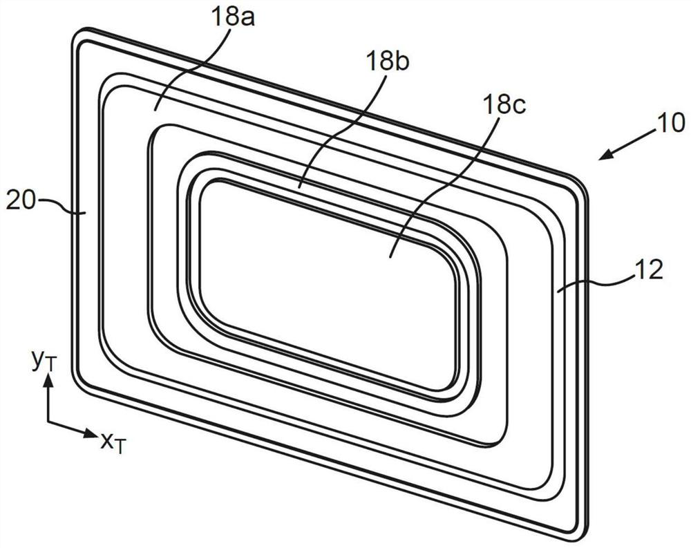
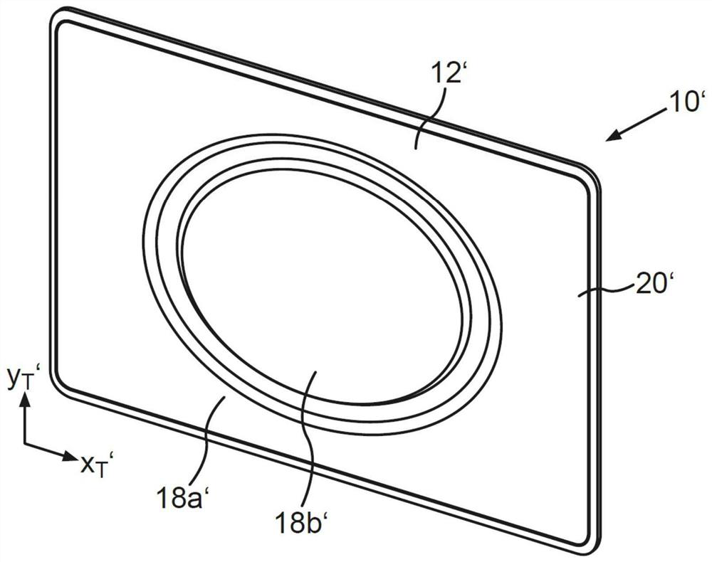
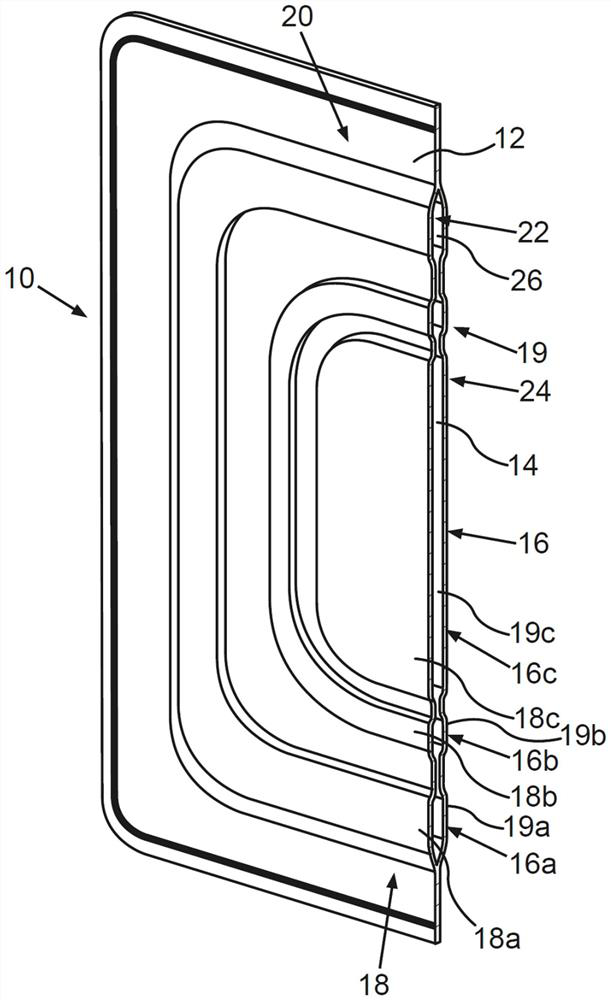
[0043] figure 1 is shown in perspective view for the battery module (in figure 1 not shown in) the separator 10. figure 2 An alternative embodiment of the separating device 10' is shown. image 3 shown in cutaway figure 1 The partition device 10. In the following, combined Figure ...


PUM


Abstract

A separating device 10 for a battery module 27. The separating device 10 includes a first separating element 12 and a second separating element 14, which are arranged congruently with respect to one another and adjacent one another. Furthermore, the first separating element 12 and the second separating element 14 enclose a chamber 16 between them, and the chamber 16 is filled with a flame-retarding and / or insulating fluid.

Description

technical field [0001] The invention relates to a separator for battery modules. The partition device comprises a first partition element and a second partition element, which are arranged side by side one above the other. The invention also relates to a battery module comprising a separator according to the invention and a motor vehicle having a battery module according to the invention. Background technique [0002] Battery modules with battery cells, especially lithium-ion cells, generate heat during the charging and discharging phases. If the temperature reaches a critical value, autoignition occurs, which can also be referred to as thermal runaway propagation / expansion. In addition, the battery cells also expand during the charge and discharge phases, which may also be referred to as bulge. In order to prevent thermal runaway of one battery cell from spreading to the nearest battery cell or damage due to expansion of the battery cells, it is known from the prior art ...

Claims


Application Information

Patent Timeline
IPC IPC(8): H01M50/204H01M50/249H01M50/256H01M50/289B60L50/64
CPCB60L50/64H01M10/61H01M10/625H01M10/647H01M10/655H01M10/6555H01M50/209H01M50/249H01M50/293H01M50/383H01M2220/20Y02T10/70Y02E60/10H01M50/403H01M50/30H01M50/44
Inventor D·赫夫纳
Owner AUDI AG
Why Eureka
Try Eureka