Object scanning device
A technology for scanning devices and objects, applied in the direction of image communication, electrical components, etc., can solve the problems of low scanning efficiency, incompleteness, unevenness of paper flatness, etc., and achieve the effect of convenient operation
- Summary
- Abstract
- Description
- Claims
- Application Information
AI Technical Summary
Problems solved by technology
Method used
Image
Examples
Embodiment approach 1
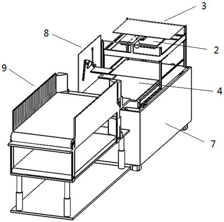
[0050] This embodiment provides an object scanning device, such as Figures 1 to 4 As shown, it is mainly composed of a paper vertical conveying device 9 , a paper pick-and-place device 8 , a paper conveying device 4 and a scanning device 1 arranged on a frame 10 in sequence.
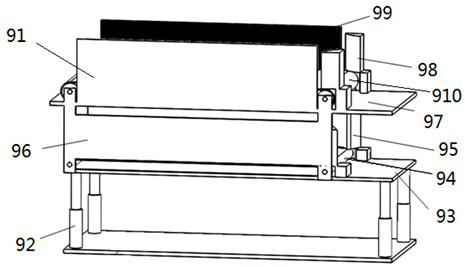
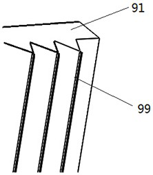
[0051] like figure 2 and 3 As shown, the paper vertical conveying device 9 includes a pick-up transmission mechanism and a placement transmission mechanism arranged up and down. In the placement transmission mechanism, the placement bottom plate 93 is horizontally installed on the top of the vertical switching push rod 92, and the placement bottom plate 93 is horizontally installed with a placement Conveyor belt 94, place conveyor belt 94 both sides and vertically be provided with and place side baffle 96, place the inlet end of side baffle 96 on both sides and be respectively equipped with arc correction piece 95, the correction piece 95 of both sides forms outward expansion trumpet shape. The pick-...
Embodiment approach 2
[0067] This embodiment is a further improvement of Embodiment 1. The main improvement is that the object scanning device of this embodiment also includes cleaning the dust on the upper and lower surfaces of the transparent placement plate 42, placing the upper scanning probe 11 and the lower scanning probe 11 for contamination. Lens 12 cleaning device 5.
[0068] like Figure 8 As shown, the cleaning device 5 includes a cleaning clamp bar 51, a slider 52, and a guide rail 53. The guide rail 53 is horizontally fixed on the frame 10 along the translation direction of the transparent placement plate 42, between the scanning area and the paper pick-and-place device 8, The slide block 52 is slidably connected to the guide rail 53 , and one end of the cleaning clamp bar 51 is horizontally connected to the slide block 52 , and the plane where the transparent placement plate 42 is located is located between the upper and lower cleaning bars of the cleaning clamp bar 51 .
[0069] Aft...
Embodiment approach 3
[0071] This embodiment is a further improvement of Embodiment 2. The main improvement is that the object scanning device of this embodiment also includes the ability to blow the paper to be scanned flat during scanning to improve the integrity, uniformity and clarity of scanning. Jetset 2, such as Figure 9 and 10 , The air injection device 2 includes an air injection box 22 and an air injection shell 21 with several air injection holes on the side of the bottom surface, and some air injection holes on the side of the air injection shell 21 form an angle of 45° with the horizontal plane. The jet box 22 is fixed on the frame 10 and communicates with the inner cavity of the jet case 21 through the jet pipe 23, and the bottom surface of the jet case 21 is arranged parallel to the transparent placement plate 42 and is located directly above the scanning area.
[0072] After the paper to be scanned on the transparent placement plate 42 is moved into the scanning area, it is just l...
PUM
 Abstract
Description
Claims
Application Information
 - R&D
- Intellectual Property
- Life Sciences
- Materials
- Tech Scout
- Unparalleled Data Quality
- Higher Quality Content
- 60% Fewer Hallucinations
Browse by: Latest US Patents, China's latest patents, Technical Efficacy Thesaurus, Application Domain, Technology Topic, Popular Technical Reports.
© 2025 PatSnap. All rights reserved.Legal|Privacy policy|Modern Slavery Act Transparency Statement|Sitemap|About US| Contact US: help@patsnap.com


