Injection equipment for injection molding machine

A technology of injection molding machine and equipment, which is applied in the direction of the device and coating of the surface coating liquid, which can solve the problems of spherical workpiece offset, processing plane loss of balance, and the smoothness of the outer contour of the workpiece. To achieve the effect of increasing friction

Active Publication Date: 2021-11-23
佛山市护尔智能科技有限公司
View PDF7 Cites 0 Cited by
  • Summary
  • Abstract
  • Description
  • Claims
  • Application Information

AI Technical Summary

Problems solved by technology

[0005] In order to solve the above-mentioned technology, when the equipment is used to dispensing and covering the workpiece with a spherical outline, due to the smoothness of the outer contour of the workpiece and the inability to fix the equipment, when the glue injection equipment reciprocates and covers the glue, the adhesion of the glue Due to the gravity and gravity, the spherical processed parts are easy to shift with the reciprocating glue covering of the injection equipment, which makes the processing plane unbalanced.

Method used


Image

  • Injection equipment for injection molding machine
  • Injection equipment for injection molding machine
  • Injection equipment for injection molding machine

Examples


Embodiment 1

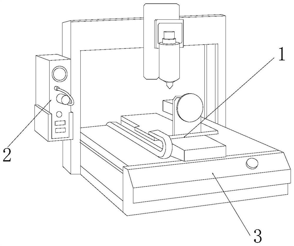
[0025] as attached figure 1 to attach Figure 5 Shown:

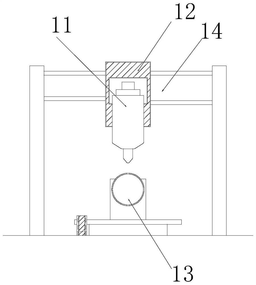
[0026] The invention provides a glue injection device for an injection molding machine, the structure of which includes a glue dispensing mechanism 1, a controller 2, and a body 3. The glue dispensing mechanism 1 is inlaid on the upper surface of the body 3, and the controller 2 is embedded and installed. On the left side of the dispensing mechanism 1, the body 3 is located under the right side of the controller 2; The glue equipment 11 is mounted on the outer end surface of the slider 12 by inlaying and engaging, and the slider 12 is inlaid and installed on the inner end of the slide rail 14, and the fixing mechanism 13 is installed directly below the glue injection equipment 11 by welding. The slide rail 14 is embedded on the upper surface of the fixing mechanism 13 .

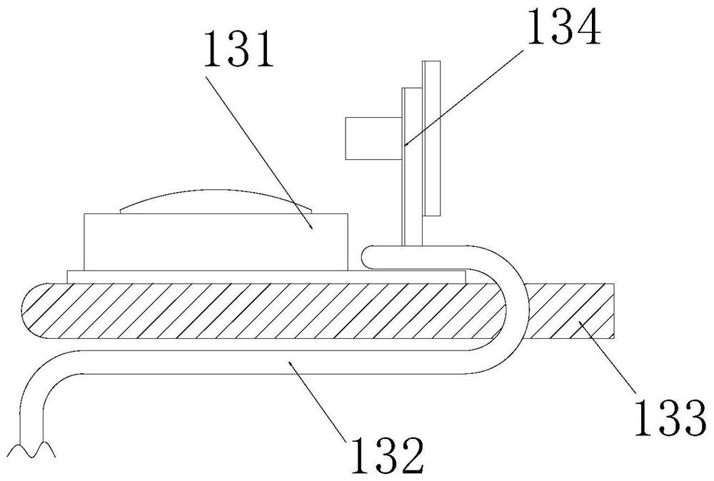
[0027] Wherein, the fixing mechanism 13 includes a fixing seat 131, a track 132, a fixing plate 133, and a focuser 134. The fixing seat 131 is inlai...

Embodiment 2

[0033] as attached Figure 6 to attach Figure 7 As shown: the matching groove 311 includes an arc groove 111, an embedding block 112, a hollow tube 113, and an air permeation mechanism 114. The solid block 112 is symmetrically installed on the left and right sides of the upper end of the hollow tube 113. The hollow tube 113 is inlaid on the inner side of the matching groove 311 at both ends of the left and right sides. The air seepage mechanism 114 is located directly below the hollow tube 113. Part of the outer contour of 113 is exposed in the inner end surface of the arc groove 111 and is made of rubber, which can be depressed inward when being squeezed to increase the friction on the surface of the spherical workpiece.

[0034] Wherein, the air permeation mechanism 114 includes an air permeation port 141, a series pipe 142, and a rubber sheet 143. On the outer surface of the lower end of the air port 141, the rubber sheet 143 is inlaid and mounted on the inner lower end ...


PUM


Abstract

The invention discloses a glue injection device for an injection molding machine. The structure includes a glue dispensing mechanism, a controller, and a machine body. The body is located under the right side of the controller; the dispensing mechanism includes injection equipment, sliders, fixing mechanisms, and slide rails. The injection equipment is inlaid and installed on the outer end of the slider, and the slider is inlaid and installed on the slide rail. At the inner side, the fixing mechanism is installed directly under the injection equipment by welding, and the rubber block evenly embedded in the outer contour of the upper end of the fitting strip increases the surface friction of the spherical workpiece at the fitting strip to prevent the workpiece from being stuck at the point During the glue covering process, due to the smoothness of the outer contour and the gravity of the glue, the spherical workpiece is turned over and the machining accuracy is lost.

Description

technical field [0001] The invention belongs to the field of equipment for injection molding, and more specifically, relates to an injection equipment for an injection molding machine. Background technique [0002] The glue injection equipment of the injection molding machine pressurizes the hot-melt glue liquid through the hydraulic equipment, so that it flows along the injection pipe to the injection port of the glue injection equipment, and then controls the closing of the injection port to squeeze the glue liquid Equipment for surfaces to be machined. [0003] Based on the inventor's discovery above, the existing methods mainly have the following deficiencies, such as: when using equipment to dispensing and covering workpieces with spherical contours, due to the smoothness of the outer contours of the workpieces and the inability to fix the equipment, When the glue injection equipment reciprocates to cover the glue, the adhesiveness and gravity of the glue will cause th...

Claims


Application Information

Patent Timeline
Patent Type & Authority Patents(China)
IPC IPC(8): B05C5/02B05C13/02
CPCB05C5/0208B05C13/02
Inventor 刘培林
Owner 佛山市护尔智能科技有限公司
Why Eureka
Try Eureka