
3D printer

A 3D printer and printing box technology, applied in the direction of 3D object support structure, grinding frame, grinding machine parts, etc., can solve the problems of affecting the printing effect, inconsistent upper and lower shapes of objects, lack of stable devices for machines, etc. To achieve the effect of optimizing the appearance

Inactive Publication Date: 2021-06-01
徐同强
View PDF0 Cites 0 Cited by
  • Summary
  • Abstract
  • Description
  • Claims
  • Application Information

AI Technical Summary

Problems solved by technology

[0004] Aiming at the deficiencies of the prior art, the present invention provides a 3D printer, which solves the problem of lack of stabilizing devices inside the machine, which will also affect the printing effect and cause waste of raw materials when encountering collisions or vibrations
Prevent the overall displacement of the item due to the adjustment of the position of the console or some external collisions during printing, resulting in inconsistency between the upper and lower shapes of the item and the production of defective products

Method used


Image

  • 3D printer
  • 3D printer
  • 3D printer

Examples


Embodiment 1

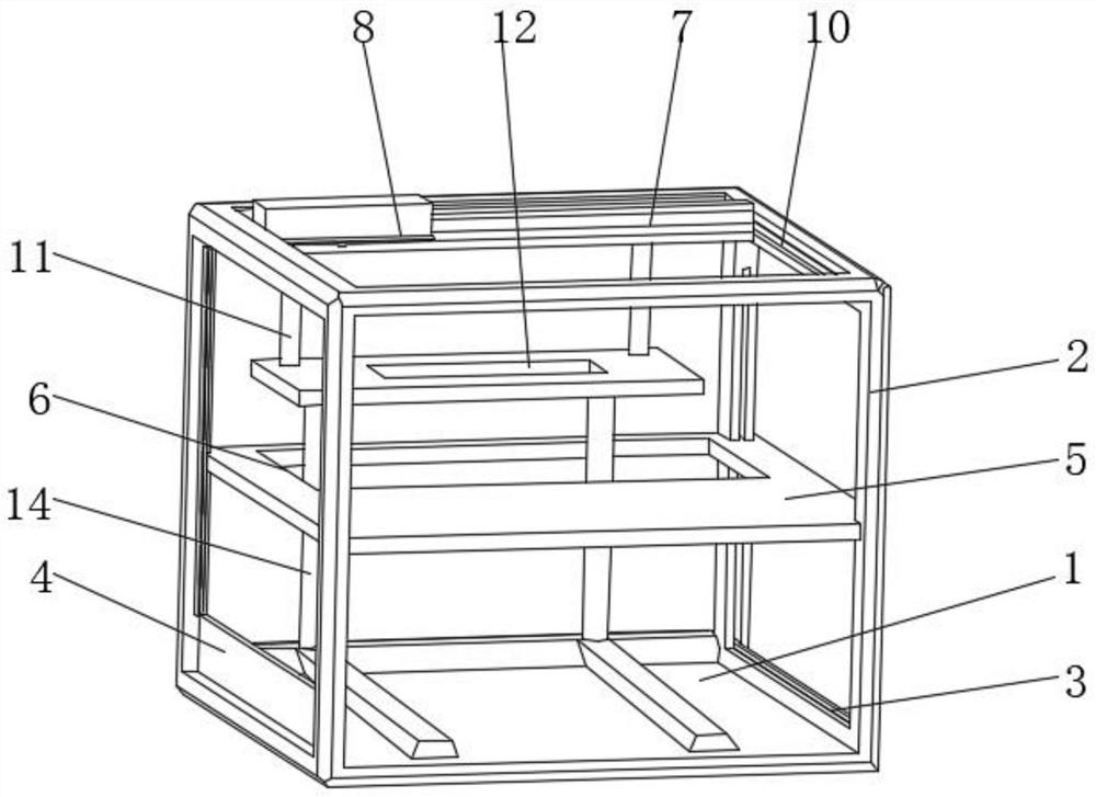
[0029] see Figure 1-2 , the invention provides a technical solution: a 3D printer. Including the printing box 1, the outer surface of the printing box 1 is evenly opened with windows 2, the inner surfaces of the windows 2 on the left and right sides are fixedly connected with the first chute 3, and the inner surface of the first chute 3 is slidably connected with the winding window 4 , the inner surface of the printing box 1 is fixedly connected with a horizontal plate 5, the outer surface of the horizontal plate 5 is provided with a through groove 6, the top and bottom of the printing box 1 are fixedly connected with a sliding track 7, and the outer surface of the top sliding track 7 is slidingly connected There is a print head 8, the bottom of the print head 8 is fixedly connected with a grinding mechanism 9, and the inner surface of the top window 2 is uniformly provided with a second chute 10, and the inner surface of the second chute 10 slides with the left and right end...

Embodiment 2

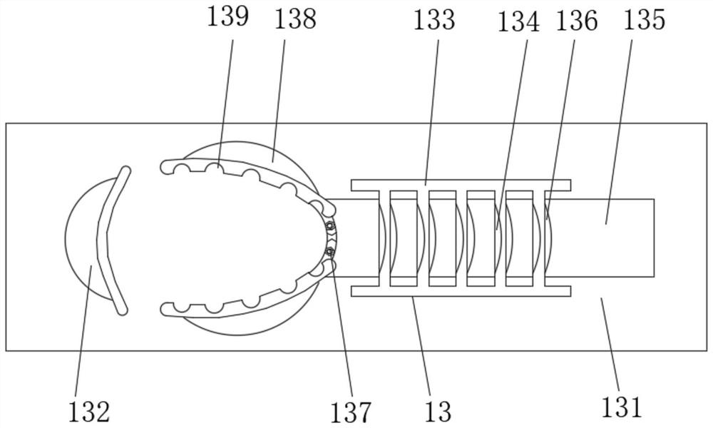
[0031] see figure 2 The present invention provides a technical solution: the fixing mechanism 13 includes a fixing frame 131, the bottom of the fixing frame 131 is fixedly connected with the top of the console 12, the left side of the fixing frame 131 is fixedly connected with an arc pad 132, and the right side of the fixing frame 131 The side is fixedly connected with a layer frame 133, and the outer surface of the layer frame 133 is uniformly provided with an arc-shaped curved surface 134, and the inner surface of the fixed frame 131 is slidably connected with a sliding rod 135 at the bottom of the layer frame 133, and the outer surface of the sliding rod 135 is fixedly connected. There is an arc-shaped card 136 , and the outer surface of the arc-shaped card 136 is engaged with the outer surface of the arc-shaped curved surface 134 .

[0032]The left side of the sliding rod 135 is fixedly connected with a magnetic rod 137, and the top and bottom of the magnetic rod 137 are ...

Embodiment 3

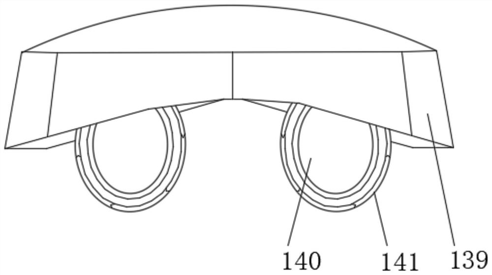
[0034] see Figure 3-5 The present invention provides a technical solution: the destab mechanism 142 includes a connecting rod a1, the outer surface of the connecting rod a1 is rotatably connected to the inner surface of the receiving groove 141, and the bottoms of the two connecting rods a1 are respectively fixedly connected with the first destab assembly (a2 and the second deburring component a3. The thorn edge outside the object is removed to optimize the appearance of the object.

[0035] The first thorn removing assembly (a2) includes a conical column a21, the outer surface of which is fixedly connected to the bottom of the connecting rod a1, and the outer surface of the conical column a21 is evenly distributed with toothed spurs a22.

[0036] The second destab assembly a3 includes an arc-shaped column a31, the top of which is fixedly connected to the bottom of the connecting rod a1, and the bottom of the arc-shaped column a31 is evenly and fixedly connected with a foot-s...


PUM


Abstract

The invention discloses a 3D printer, and relates to the technical field of 3D printers. The 3D printer comprises a printing box, wherein windows are evenly formed in the outer surface of the printing box, first sliding grooves are fixedly connected to the inner surfaces of the windows on the left side and the right side, rolling windows are slidably connected to the inner surfaces of the first sliding grooves, a transverse plate is fixedly connected to the inner surface of the printing box, a through groove is formed in the outer surface of the transverse plate, sliding rails are fixedly connected to the top and the bottom of the printing box, and a printing head is slidably connected to the outer surface of the sliding rail at the top. An operation table capable of moving back and forth is arranged inside the printing box, when the printing head performs printing, the corresponding position of the operation table can be adjusted along with the printing of the printing head, then a produced object can be fixed through a fixing mechanism, and the situation that due to adjustment of the position of the operation table or some external collisions during printing, the whole object moves, the upper and lower shapes of the object are not consistent, defective products are produced, and raw materials are wasted is prevented.

Description

technical field [0001] The invention relates to the technical field of 3D printers, in particular to a 3D printer. Background technique [0002] 3D printing is a kind of rapid prototyping technology, also known as additive manufacturing. It is a technology based on digital model files and using bondable materials such as powdered metal or plastic to construct objects by layer-by-layer printing. . 3D printing is usually achieved using digital technology material printers. It is often used to make models in the fields of mold manufacturing and industrial design, and is gradually used in the direct manufacture of some products. There are already parts printed using this technology. [0003] 3D printing technology is gradually being widely used, such as making models that are easy for patients to swallow and for experimental groups to study and make models. The existing 3D printers can print a real object according to drawings and materials, but when the 3D printer is working,...

Claims


Application Information

Patent Timeline
Patent Type & Authority Applications(China)
IPC IPC(8): B29C64/20B29C64/245B29C64/35B29C64/379B22F12/00B22F10/66B24B19/00B24B19/22B24B41/04B24B41/02B33Y30/00B33Y40/00B33Y40/20
CPCB22F3/003B22F3/24B22F2003/247B24B19/00B24B19/22B24B41/02B24B41/04B33Y30/00B33Y40/00B29C64/20B29C64/245B29C64/35B29C64/379B33Y40/20
Inventor 徐同强
Owner 徐同强
Learn More