Spinning roller supporting structure with self-locking limiting structure

A technology of support structure and limit structure, which is applied in the directions of winding strips, thin material handling, transportation and packaging, etc., and can solve problems such as poor versatility and cumbersome operation

Inactive Publication Date: 2021-06-01
马鞍山聚儒信息科技有限公司
View PDF1 Cites 1 Cited by
  • Summary
  • Abstract
  • Description
  • Claims
  • Application Information

AI Technical Summary

Problems solved by technology

[0006] The object of the present invention is to provide a textile roller support structure with a self-locking position-limiting structure, to solve the existing textile roller fixing device on the market proposed by the above-mentioned background technology, which is mainly provided with a The fixed block cover can be disassembled, and the auxiliary transmission groove inside the fixed block cover is combined with the transmission groove at the upper end of the support table to realize the clamping and limiting of both ends of the textile roller. When it is necessary to disassemble or replace the textile roller on the support table, It is necessary to disassemble the bolts on the fixed block cover one by one, and then remove the fixed block cover. Therefore, it is only possible to clamp the textile roll of a single-size support shaft, and the problem of poor versatility

Method used


Image

  • Spinning roller supporting structure with self-locking limiting structure
  • Spinning roller supporting structure with self-locking limiting structure
  • Spinning roller supporting structure with self-locking limiting structure

Examples


Embodiment Construction

[0029] Based on the embodiments of the present invention, all other embodiments obtained by persons of ordinary skill in the art without making creative efforts belong to the protection scope of the present invention.

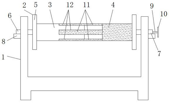
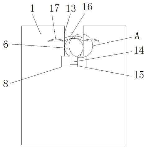
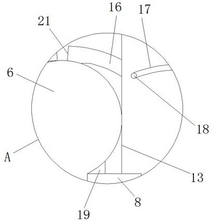
[0030] see Figure 1-8, the present invention provides a technical solution: a textile roller support structure with a self-locking limit structure, including a support structure body 1, a textile roller 2, a first roller body 3, a second roller body 4, a protective edge 5, a A support shaft 6, a second support shaft 7, a limit bracket 8, an adjustment rod 9, an adjustment wheel 10, a connection bar 11, a connection groove 12, a placement port 13, a limit block 14, a limit card groove 15, a pressure Tightening part 16, turning mouth 17, toggle lever 18, push seat 19, turning groove 20, pressing head 21, pressing groove 22, rotating shaft 23, sliding opening 24, support column 25, connecting frame 26, spring 27, Adjusting sleeve 28, threaded hole 29, bearing 30...


PUM


Abstract

The invention discloses a spinning roller supporting structure with a self-locking limiting structure. The spinning roller supporting structure comprises a supporting structure body, a spinning roller, a protective edge, a first supporting shaft, a second supporting shaft, an adjusting wheel, a connecting frame, a spring, an adjusting sleeve, a threaded hole, a bearing and sliding grooves; the spinning roller is arranged on the supporting structure body; a first roller body is arranged on one side of the spinning roller; connecting strips are arranged on the inner side roller body of a second roller body at equal intervals; the second roller body is connected with connecting grooves in the inner side of the first roller body through the connecting strips; and protruding strips on the two sides of the connecting strips are located in the sliding grooves in the connecting grooves. According to the spinning roller supporting structure with the self-locking limiting structure, through improvement of an existing spinning roller supporting structure, rapid clamping operation on supporting shafts at the two ends of the spinning roller can be achieved, pushing aside of a pressing piece can be achieved through arrangement of a poke rod outside the pressing piece, then clamping work of the pressing piece on the supporting shafts is relieved, and the supporting shafts on the two sides of the spinning roller can be moved out conveniently and quickly.

Description

technical field [0001] The invention relates to the technical field of textile roll support structures, in particular to a textile roll support structure with a self-locking position-limiting structure. Background technique [0002] The textile roller is mainly a drum-like structure for winding and collecting the textile yarn or the woven fabric. For example, the application number of the comparative document: CN202020051458.0, and the authorized announcement date: 20201103. A textile roller for textile use, which involves In the field of textile processing accessories, it includes a support table, a first fixed block is fixedly arranged on one side of the upper end of the support table, a second fixed block is fixedly arranged on the other side of the support table, and the first fixed block is connected with the second fixed block. A collection roller is arranged between the blocks, and a transmission shaft is arranged inside the collection roller, one end of the transmiss...

Claims


Application Information

Patent Timeline
IPC IPC(8): B65H19/30B65H75/24B65H75/14B65H18/06
CPCB65H18/06B65H19/30B65H75/14B65H75/241B65H2701/174
Inventor 胡秀凤
Owner 马鞍山聚儒信息科技有限公司
Why Eureka
Try Eureka